Touch panel

a touch panel and large-scale technology, applied in the field of touch detection, can solve the problems of limiting the trend toward large-scale touch panels, attenuation of relevant signals, etc., and achieve the effect of reducing rc loading and avoiding signal attenuation

Active Publication Date: 2014-09-16
AU OPTRONICS CORP
View PDF22 Cites 1 Cited by
  • Summary
  • Abstract
  • Description
  • Claims
  • Application Information

AI Technical Summary

Benefits of technology

[0008]Accordingly, the present invention is directed to a touch panel, can decrease a RC loading and avoid signal attenuation.
[0016]Since the touch panel are divided into different regions and the sensing units of the different regions are electrically coupled to different driving lines or different sensing lines, that is anyone of the driving lines or the sensing lines is electrically coupled to less sensing units, therefore the present invention can decrease the RC loading and reduce signal attenuation.

Problems solved by technology

Thus it is prone to a problem of excessive RC loading and causing attenuation of relevant signals.
Furthermore, the larger of the size of the touch panel 10, the more serious of the above-mentioned problem.
Thus it greatly limits the trend toward large sized touch panels.

Method used


Image

  • Touch panel
  • Touch panel
  • Touch panel

Examples


Embodiment Construction

[0023]It is to be understood that other embodiment may be utilized and structural changes may be made without departing from the scope of the present invention. Also, it is to be understood that the phraseology and terminology used herein are for the purpose of description and should not be regarded as limiting. The use of “including,”“comprising,” or “having” and variations thereof herein is meant to encompass the items listed thereafter and equivalents thereof as well as additional items. Unless limited otherwise, the terms “connected,”“coupled,” and “mounted,” and variations thereof herein are used broadly and encompass direct and indirect connections, couplings, and mountings. Accordingly, the drawings and descriptions will be regarded as illustrative in nature and not as restrictive.

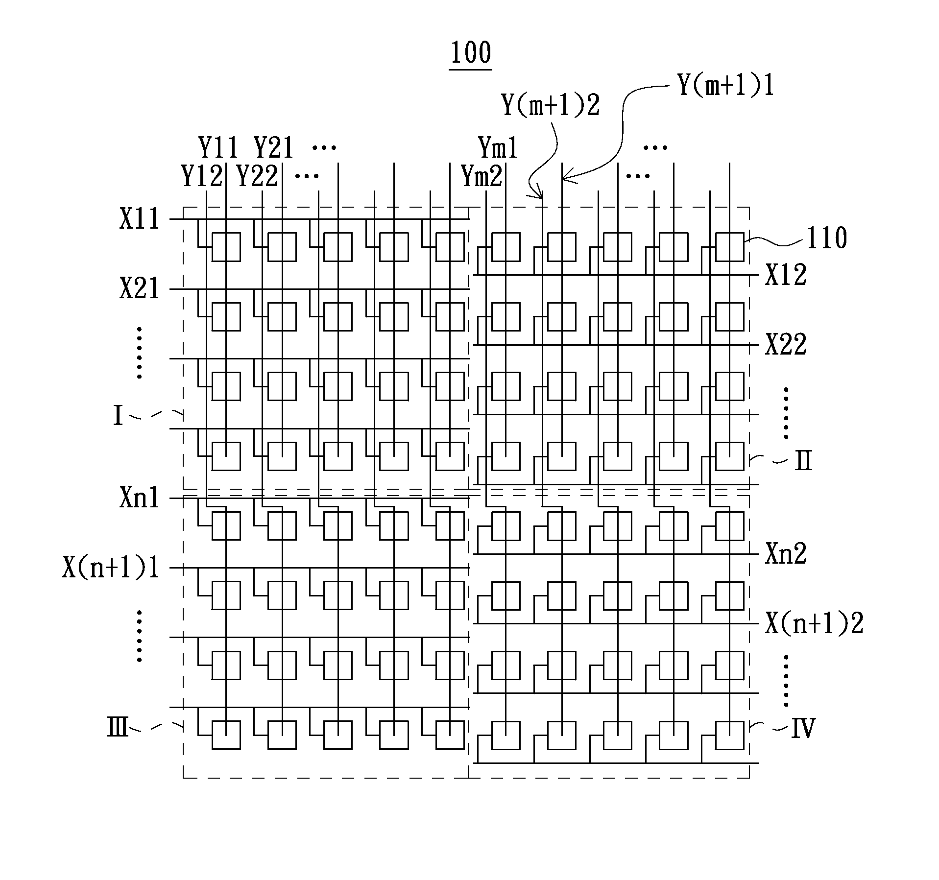
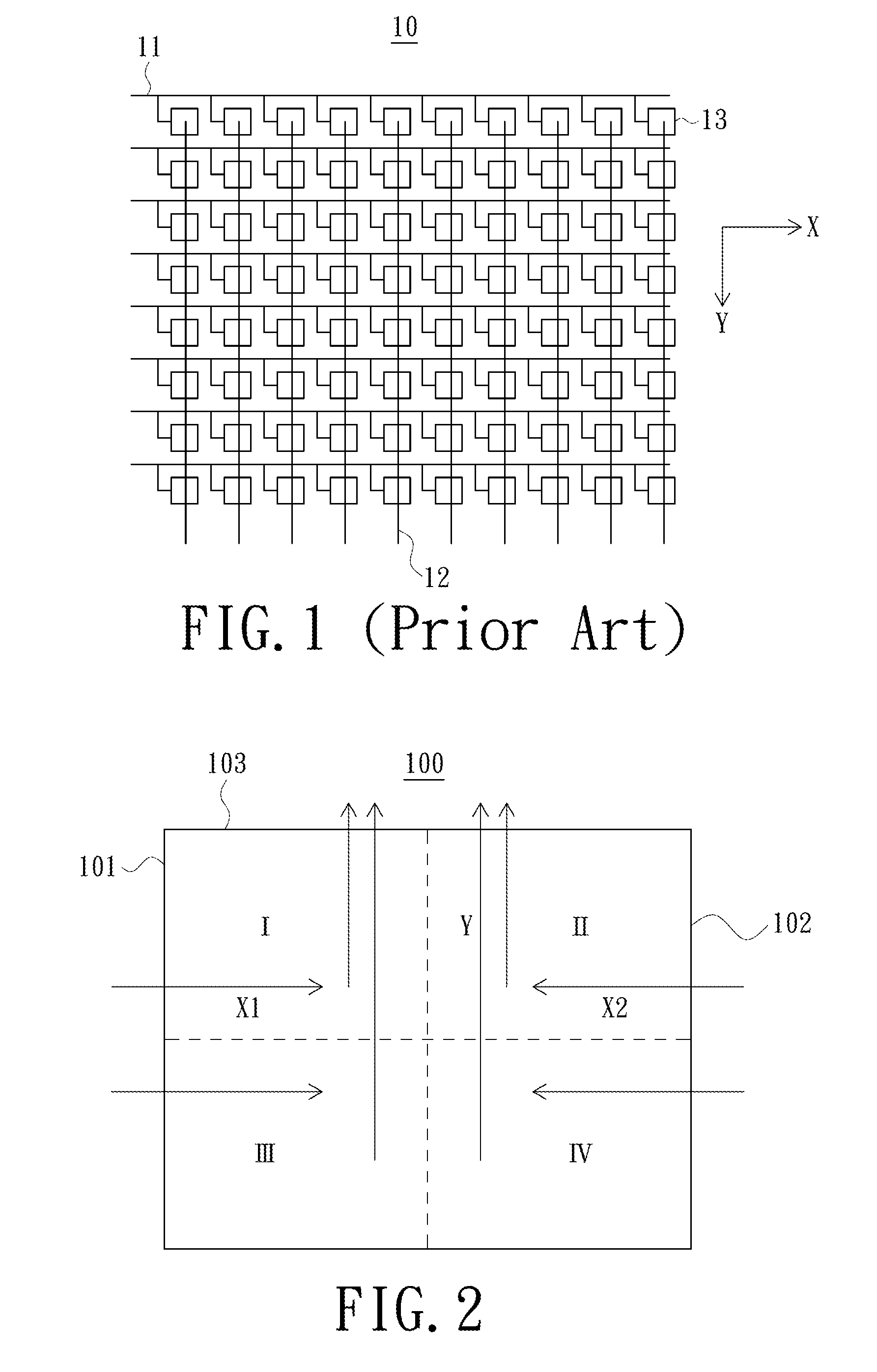
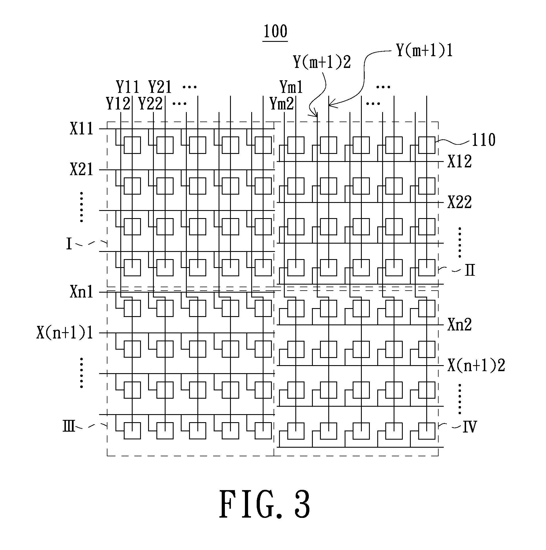
[0024]Referring to FIGS. 2 and 3, FIG. 2 is a schematic view of a touch panel in accordance with an exemplary embodiment of the present invention, and FIG. 3 is a schematic view of a detailed struct...


PUM


Abstract

A touch panel includes a plurality of driving lines, a plurality of sensing lines and a plurality of sensing units. The sensing lines are arranged intersecting with the driving lines. The sensing units are arranged in an array, and each of the sensing units is electrically coupled to a corresponding one of the driving lines and a corresponding one of the sensing lines. The driving lines or the sensing lines only pass through a single side of the touch panel.

Description

BACKGROUND[0001]1. Technical Field[0002]The present invention generally relates to the touch detection field, and more particularly to a touch panel with large size.[0003]2. Description of the Related Art[0004]With the rapid development of the science and technology, touch panels are widely applied into various electronic devices and become a novel human-machine interface since it is more intuitional and humanistic in use.[0005]Referring to FIG. 1, which is a schematic structural view of a conventional touch panel. As shown in FIG. 1, the touch panel 10 comprises a plurality of driving lines 11, a plurality of sensing lines 12 and a plurality of sensing units 13. The driving lines 11 are arranged intersecting with the sensing lines 12. The sensing units 13 are arranged in an array, and each of the sensing units 13 is electrically coupled to a corresponding one of the driving lines 11 and a corresponding one of the sensing lines 12, such that each of the sensing units 13 can be provi...

Claims


Application Information

Patent Timeline
Patent Type & Authority Patents(United States)
IPC IPC(8): G06F3/041
CPCG06F3/041G06F3/0416G06F3/04166
Inventor WANG, YI-LONGHSIEH, MING-LUNYU, JIAN-SHENCHIANG, MIN-FENG
Owner AU OPTRONICS CORP
Why Eureka
Try Eureka