Load device for vehicles

a technology for loading devices and vehicles, applied in the direction of loading/unloading vehicle arrangment, load accommodation, transportation items, etc., can solve the problems of easy loading of items, inability to place securing devices, and limited positioning capability of load securing devices, so as to increase the positioning possibilities of load holding elements and good variation possibilities

Inactive Publication Date: 2014-10-14
GM GLOBAL TECH OPERATIONS LLC
View PDF7 Cites 6 Cited by
  • Summary
  • Abstract
  • Description
  • Claims
  • Application Information

AI Technical Summary

Benefits of technology

[0006]According to one aspect of the present invention, a load device for a vehicle comprises at least one elongate guide rail which is formed with a slide groove, said guide rail being arranged to receive at least one load holding element which is displaceable relative to the guide rail along said slide groove during positioning of said load holding element in a desired position, which guide rail has a first slide groove portion with a first direction of extension and a second slide groove portion with a second direction of extension deviating from the first, said slide groove portions continuously merging into each other. One advantage of this design is that a load compartment of a vehicle provided with such a load device can be optionally adjusted in a large number of ways to allow storage and load securing of items that are to be transported. A slide groove which has at least two slide groove portions with different extensions relative to each other advantageously allows the load holding element to be arranged with an extension in a number of different directions by being displaced along the slide groove. In addition, the design of the load device enables the load holding element to be easily placed in a storage position along the slide groove so as to make the major part of the load compartment of the vehicle available.
[0018]To provide a robust and durable load device, the guide rail is suitably arranged to be attached to the load compartment floor of a vehicle. According to one embodiment, the guide rail can suitably be arranged along the edge of an openable and closable portion of the load compartment floor of a vehicle. By this design, a car manufacturer can optionally choose to equip a vehicle with a load device by choosing the openable and closable portion of the floor. Thanks to this design, it is also easy for a vehicle owner to equip his vehicle with a load device by obtaining and installing an openable and closable floor portion provided with a guide rail. To make it possible to mount a guide rail in a reliable and stable manner, the guide rail is suitably provided with attachment means which are arranged to secure said guide rail relative to the load compartment floor of a vehicle.

Problems solved by technology

However, these load securing devices have limited positioning capability.
Moreover, in most cases, these load securing devices cannot be placed in such a way that it will be easy to load items into the load compartment of a vehicle.
Nor is it possible, in many cases, to store such load securing devices in a desirable manner in the load compartment of the vehicle when not used for securing loads.

Method used


Image

  • Load device for vehicles
  • Load device for vehicles
  • Load device for vehicles

Examples


Embodiment Construction

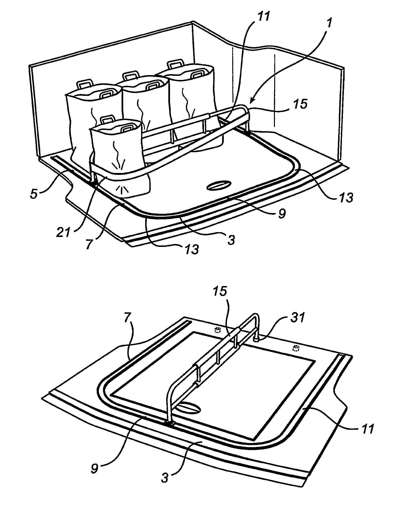
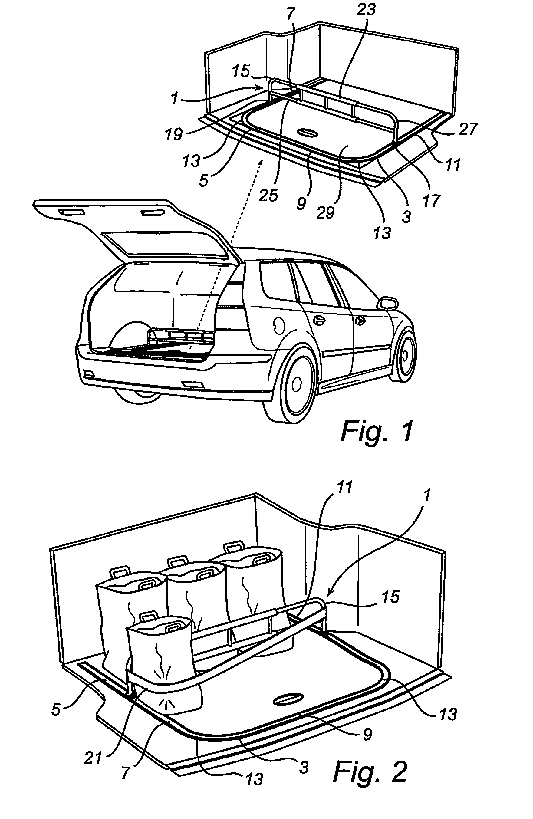
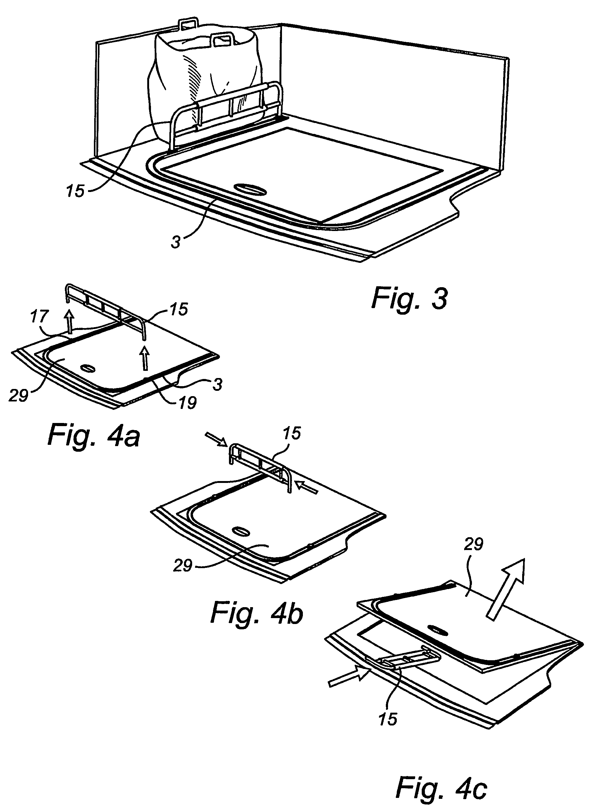
[0029]FIGS. 1 and 2 are perspective view of a load device 1 for a vehicle according to one embodiment of the invention. The load device 1 according to FIGS. 1 and 2 is arranged in a load compartment of a car, in this case an estate car. The load device 1 comprises an elongate guide rail 3 which is formed with a slide groove 5. The guide rail 3 according to FIG. 1 and its associated slide groove 5 has a U-shaped extension with a first and a third slide groove portion 7, 11 extending in the driving direction of the vehicle and a second slide groove portion 9 substantially extending transversely to the driving direction of the vehicle between the first and the third slide groove portion 7, 11. The ends of the second slide groove portion 9 continuously merge into, respectively, the first and the third slide groove portion 7, 11. Accordingly, the first, second and third slide groove portions 7, 9, 11 of the guide rail 3 form a continuous and integral slide groove 5 along substantially th...


PUM


Abstract

The present invention relates to a load device (1) for a vehicle, comprising at least one elongate guide rail (3) which is formed with a slide groove (5), said guide rail (3) being arranged to receive at least one load holding element (15) which is displaceable relative to the guide rail (3) along said slide groove (5) during positioning of said load holding element (15) in a desired position, said guide rail (3) having a first slide groove portion (7) with a first direction of extension and a second slide groove portion (9) with a second direction of extension deviating from the first, said slide groove portions (7, 9) continuously merging into each other.

Description

FIELD OF THE INVENTION[0001]The present invention relates to a load device for a vehicle, comprising at least one elongate guide rail which is formed with a slide groove, said guide rail being arranged to receive at least one load holding element which is displaceable relative to the guide rail along said slide groove during positioning of said load holding element in a desired position.TECHNICAL BACKGROUND[0002]The load compartment of most vehicles has a loading capacity, i.e. floor area in this case, sufficient to accommodate and transport a number of items, such as carrier bags, cardboard containers, bags or other luggage. In many cases, the items loaded do not take up the entire loading area and therefore, when driving a loaded vehicle, these items often “roll” around in the load compartment if not secured in some way. An easy way of securing a load is to simply equip the load compartment with loops, in which straps intended to hold the load can be fastened.[0003]A load securing...

Claims


Application Information

Patent Timeline
Patent Type & Authority Patents(United States)
IPC IPC(8): B60P7/08B60R7/02
CPCB60R7/02B60P7/0892B60P7/08B60R5/04
Inventor ARO, LASSEWIDEN, MARTIN C.
Owner GM GLOBAL TECH OPERATIONS LLC
Why Eureka
Try Eureka