Filter and fuel assembly for a light-water nuclear reactor

a technology of light-water nuclear reactor and fuel assembly, which is applied in the direction of reactor fuel elements, thermal reactors, separation processes, etc., can solve the problems of defect fuel having to be changed, reactor operation shut down, and nuclear fuel, i.e. uranium, to achieve the effect of good balance between flow resistance and catching ability, increasing pressure drop, and limited flow resistan

Inactive Publication Date: 2004-04-15
WESTINGHOUSE ATOM
View PDF17 Cites 6 Cited by
  • Summary
  • Abstract
  • Description
  • Claims
  • Application Information

AI Technical Summary

Benefits of technology

0017] According to a further embodiment of the invention, the first channel section has a flow area of, which is essentially equal to the area of flow in the intermediate section. Thus, a good balance between flow resistance and catching ability is achieved.
0018] According to a further embodiment of the invention, two neighbouring channels have intermediate sections arranged at different distances from the inlet end. This is advantageous since it is possible to locate the channels closer to each other so that more channels can be arranged on the same surf...

Problems solved by technology

If waste material or other particles are allowed to come with the cooling water in the reactor core, they may cause damages to the cladding of the fuel rods, which might lead to such damages that the nuclear fuel, i.e. uranium, will leak out into the cooling water.
At larger damages, the operation of the reactor has to be shut down and the defect fuel has to be changed.
Such a change is time consuming and expensive.
Waste material and other particles may, of course, also cause damages to other components in the nuclear plant, such as pumps.
Particularly troublesome particles are such with an extended shape, i.e. narrow wires or shavings, which might be as small as about 10 mm long.
Such particles tend ...

Method used


Image

  • Filter and fuel assembly for a light-water nuclear reactor
  • Filter and fuel assembly for a light-water nuclear reactor
  • Filter and fuel assembly for a light-water nuclear reactor

Examples


Embodiment Construction

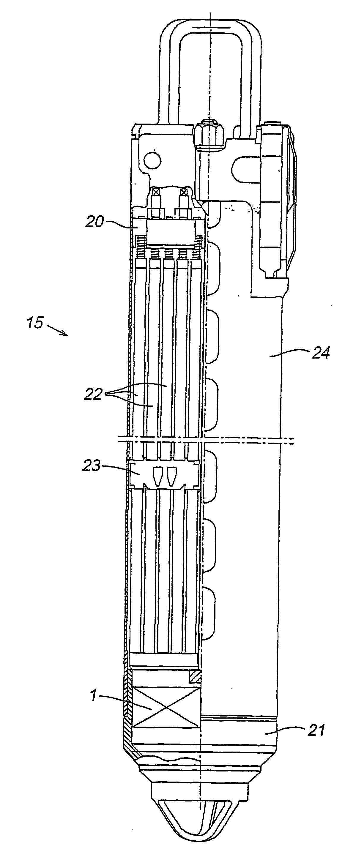
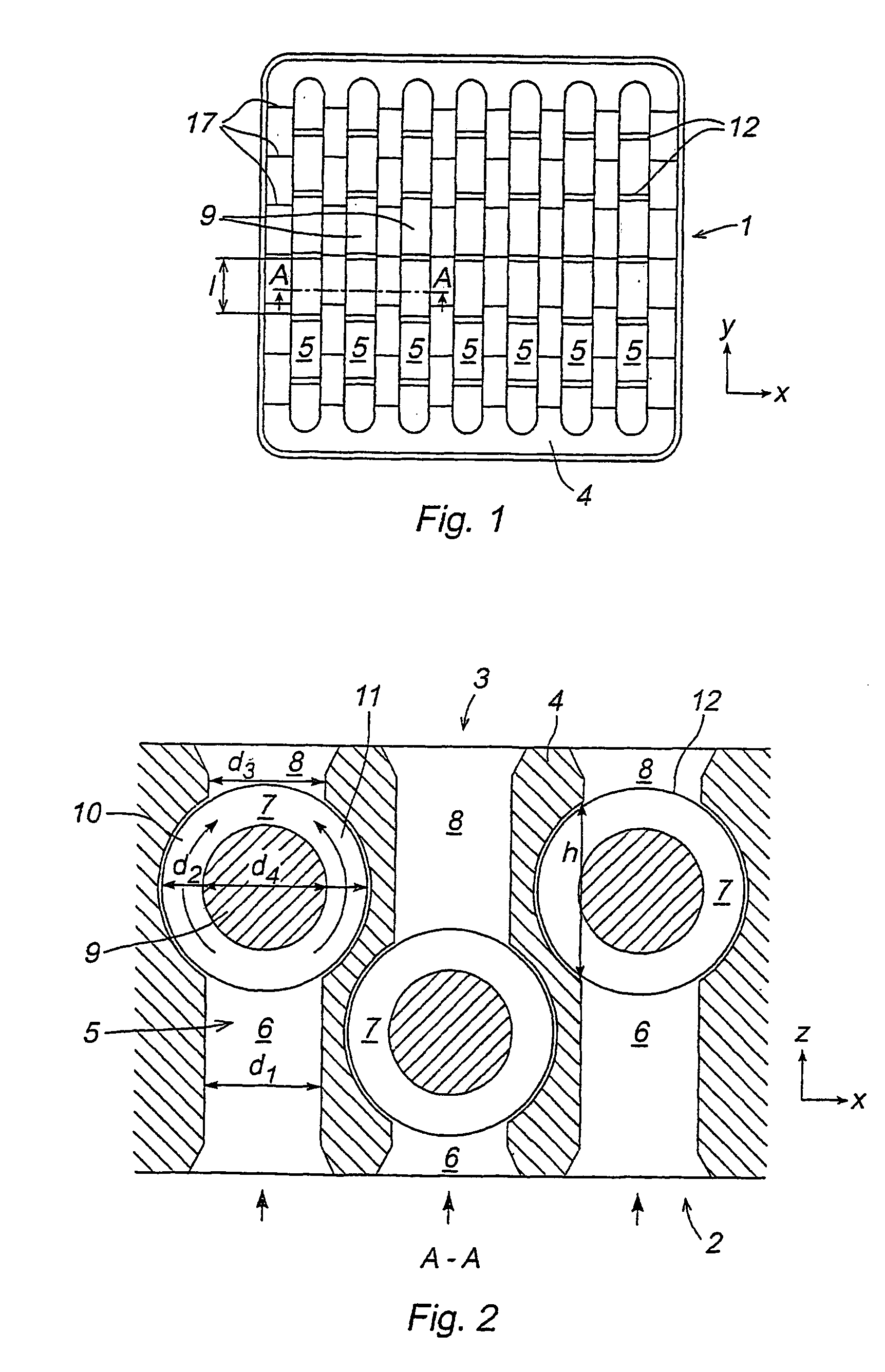
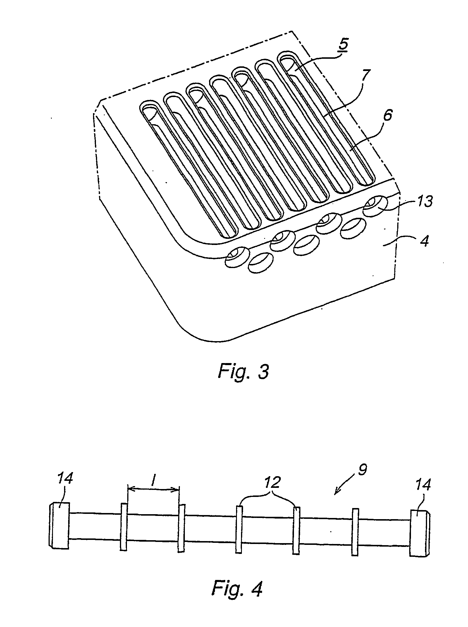
[0029] The FIGS. 1 and 2 show a filter 1 for separating particles from the cooling water in a nuclear plant. The filter 1 has an inlet end 2 and an outlet end 3. The cooling water may thus flow through the filter 1 from the inlet end 2 to the outlet end 3 in a main flow direction z.

[0030] The filter 1 comprises an essentially rectangular solid plate 4, in which a number of elongated spaces 5 are arranged. The plate 4 is made of a metallic material, for example stainless steel. The spaces 5 are parallelly arranged and extend along the main part of the length of the plate 4 in a direction y transversely to the flow direction. The spaces 5 extend through the entire plate 4 in the flow direction z and have openings in the inlet end 2 and the outlet end 3 so that the cooling water can flow through the filter 1. The spaces 5 define channels, through which the cooling water has to pass before reaching the fuel rods.

[0031] As shown in FIG. 2 the spaces 5 comprise a first section 6, an inter...


PUM

PropertyMeasurementUnit
Flow rateaaaaaaaaaa
Lengthaaaaaaaaaa
Areaaaaaaaaaaa

Abstract

A filter for separating particles from cooling water in a nuclear plant of light water model. The filter has an inlet end (2) and an outlet end (3) and allow flowing through of the cooling water in a flow direction % from the inlet end to the outlet end. The filter comprises a plurality of channels (5) extending mainly in the flow from the inlet end to the outlet end. Each of the channels comprise a first (6) channel section provided closer to the inlet end, a second (8) channel section arranged closer to the outlet end, and an intermediate section (7) provided between the first and the second channel section. The intermediate section (7) has an extension d2 in a direction x transversely to the flow direction, which is essentially larger than the extension d2.

Description

[0001] The present invention relates to a filter for separating particles from the cooling water in a nuclear plant of a light-water model, the filter having an inlet end and an outlet end and is arranged for permitting flowing-through of the cooling water in a main flow direction from the inlet end to the outlet end, the filter comprising a plurality of channels mainly extending in the flow direction from the inlet end to the outlet end, each of the channels comprising a first channel section provided closer to the inlet end, a second channel section arranged closer to the outlet end an intermediate section provided between the first and the second channel section. The invention also relates to a fuel assembly according to the preamble of the claim 17.[0002] The invention will be described in an application for nuclear plants, for purifying the cooling water flowing through a nuclear plant of light-water type, from waste material and other particles. However, the invention is not l...

Claims


Application Information

Patent Timeline
IPC IPC(8): G21C3/30G21C3/32G21C3/33
CPCG21C3/3206Y02E30/40G21Y2004/303G21Y2002/303Y02E30/30
Inventor NYLUND, OLOV
Owner WESTINGHOUSE ATOM
Why Eureka
Try Eureka