Stapler with stack height compensation

a technology of stack height compensation and stapler, which is applied in the field of staplers, can solve the problems of degrading the integrity of the housing and inherently difficult control of the compensation, and achieve the effect of simplifying and compacting the construction of the stack height compensation

Active Publication Date: 2007-11-27
ACCO BRANDS USA LLC
View PDF31 Cites 6 Cited by
  • Summary
  • Abstract
  • Description
  • Claims
  • Application Information

AI Technical Summary

Benefits of technology

[0004]Some prior art stapler designs place the stack height compensation in or about linkages that are spaced from, yet ultimately driven by the rotational gear or drive train. The present invention provides an improved stack height compensation construction that more closely accompanies, or is integrated with the rotational drive train. In one embodiment, a resilient member directly supports and constrains the movement of a portion of the rotational drive train. This arrangement provides for a simplified and more compact powered stapler.
[0005]Other prior art staplers compensate for stack height variation by permitting flexing or resilient deformation of the housing surrounding the stapler engine. In some instances, resilient bushings are directly supported by the housing of the stapler. This makes the compensation inherently difficult to control, and over time, stresses on the housing can degrade the integrity of the housing. The invention provides a stapler engine construction that incorporates stack height compensation completely within the stapler engine, yet without additional linkages. This construction provides a simplified yet robust and durable stapler design in which the stack height compensation is independent of the surrounding housing.
[0007]In one embodiment, the rotational drive train is at least partially supported by a frame and includes a motor operable to drive a drive member. The drive member is mounted for rotation with a shaft supported by the frame and is configured to engage a driven member of the driving assembly. The ends of the shaft extend through elongated apertures in the frame and are received in resilient members coupled to the frame adjacent the elongated apertures. Together, the resilient members and the elongated apertures allow movement of the shaft and drive member relative to the frame to provide stack height compensation for the stapler.
[0008]In particular, the resilient members support the ends of the shaft in a first position with respect to the elongated apertures. However, as the stack height increases, the resilient members permit the ends of the shaft to move away from the first position within the elongated apertures during the stapling operation, and then return the ends of the shaft to the first position when stapling is completed. By permitting the drive shaft to move or float in this manner, excessive loading on the motor is substantially prevented, thereby reducing the occurrence of stapling malfunctions.

Problems solved by technology

This makes the compensation inherently difficult to control, and over time, stresses on the housing can degrade the integrity of the housing.

Method used


Image

  • Stapler with stack height compensation
  • Stapler with stack height compensation
  • Stapler with stack height compensation

Examples


Embodiment Construction

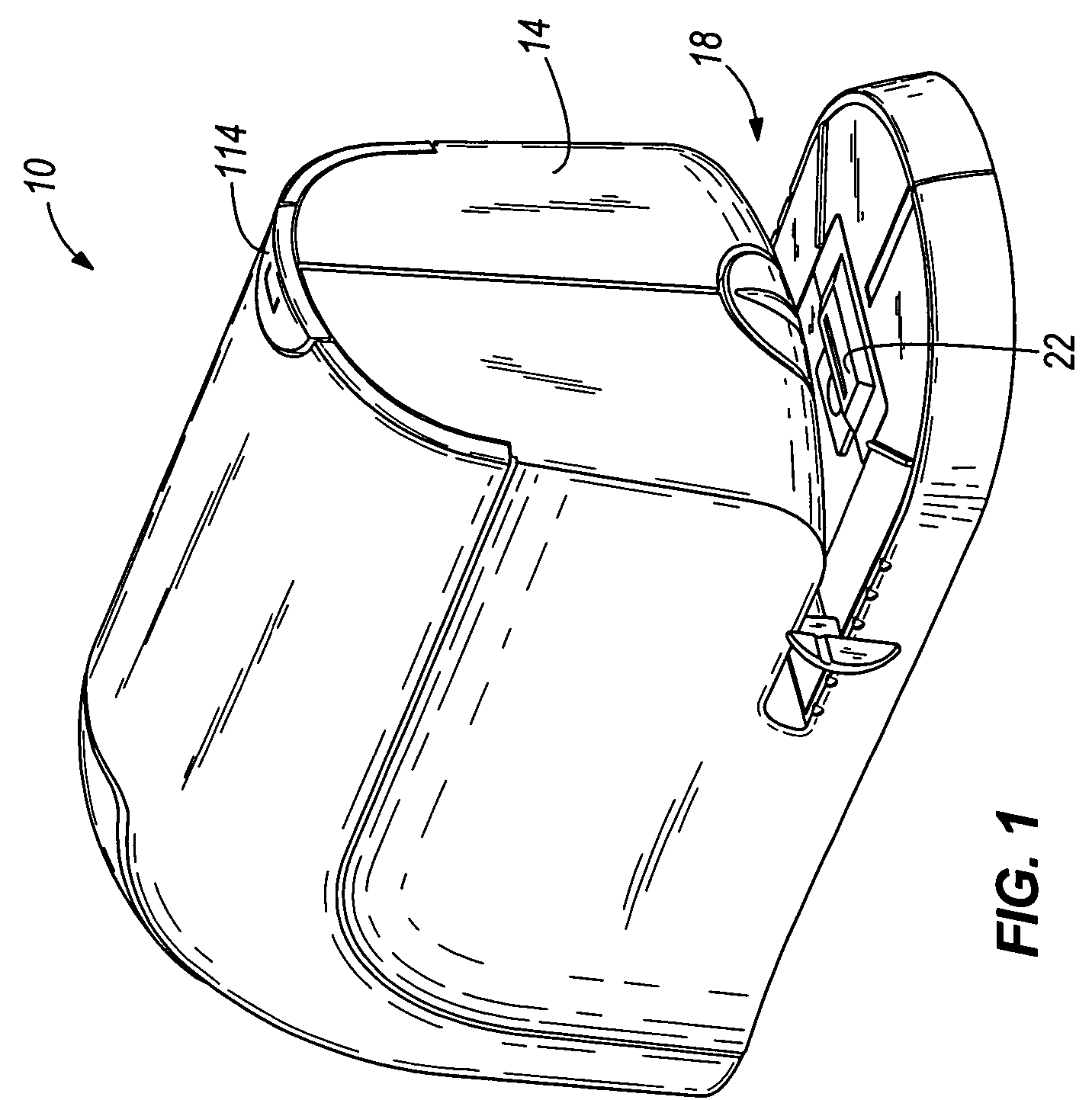
[0026]FIGS. 1-12 illustrate a stapler 10 embodying the present invention. The stapler 10 is a powered or electric stapler operable with an AC to DC current supply, a DC current supply, or both. With reference to FIG. 1, the stapler 10 includes a housing 14 defining a slot 18 configured to receive a stack of sheets S (see FIGS. 7, 9, and 11) to be stapled. An anvil 22 is supported by the housing 14 in a location opposite to the staple ejection point. The anvil 22 receives the legs of the staples driven through the stack of sheets S and clinches the legs in a known manner.

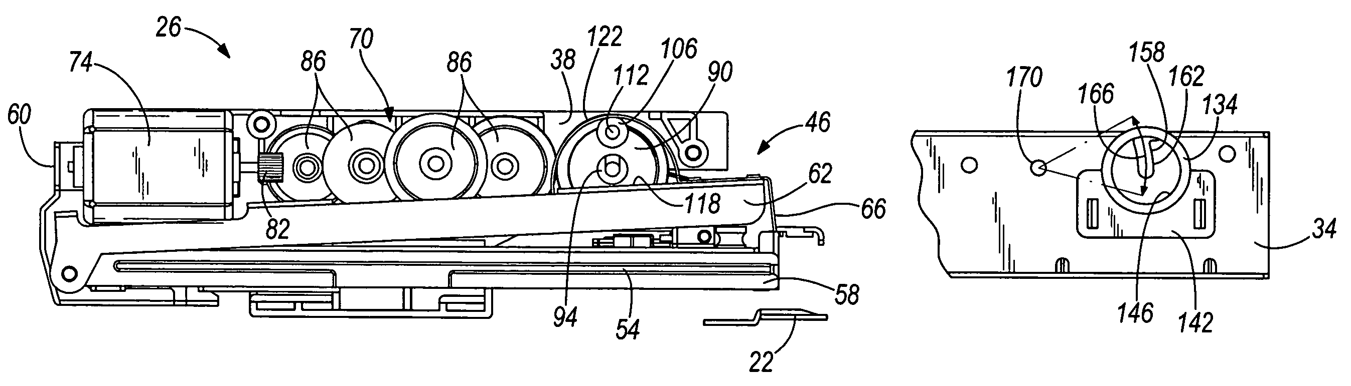
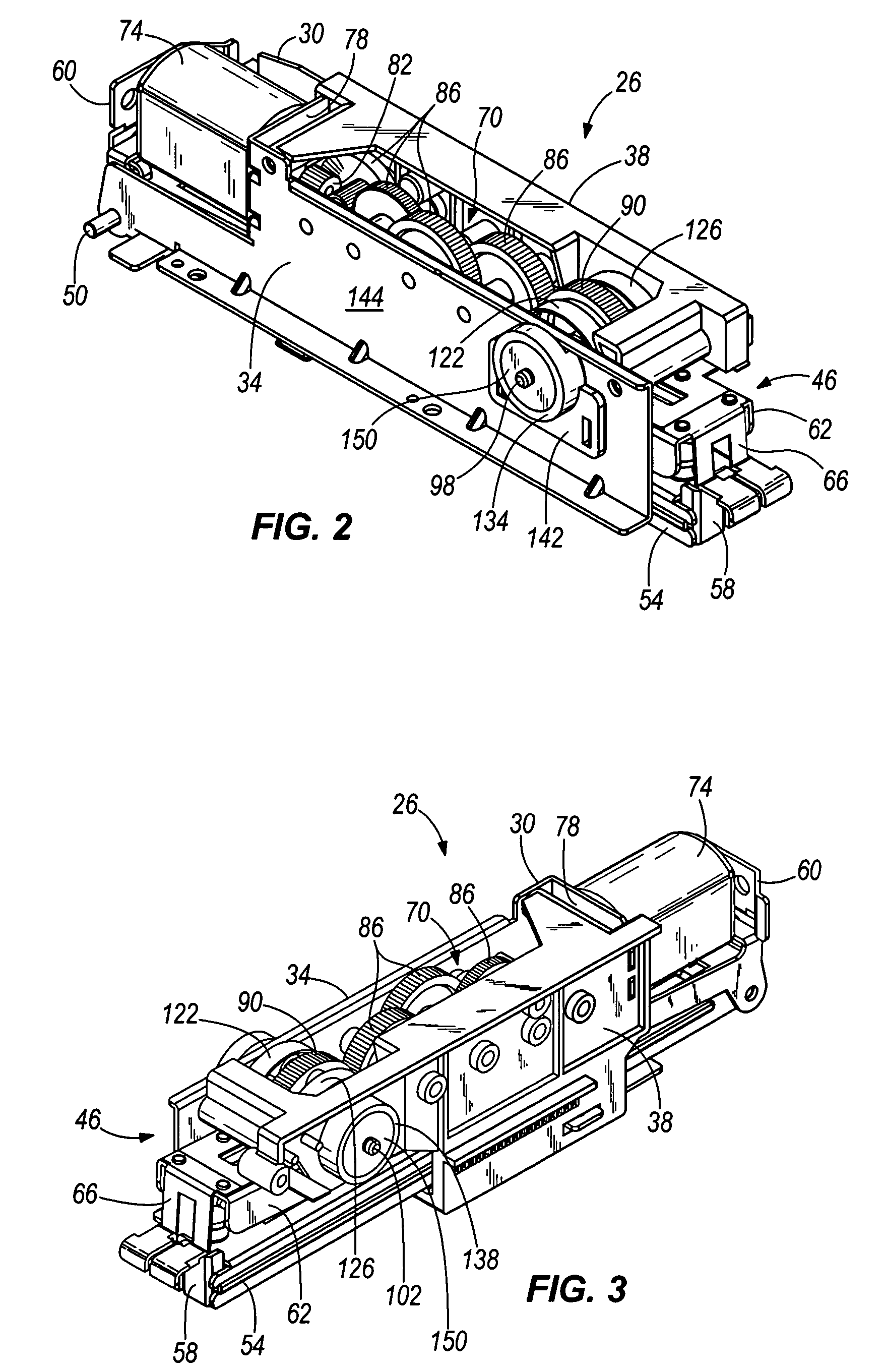
[0027]Referring now to FIGS. 2-4, the stapler 10 includes a stapler engine 26 housed within the housing 14. The stapler engine 26 is a generally self-contained unit having a frame 30 including first and second gear box plates 34 and 38, respectively. The gear box plates 34, 38 are fixedly mounted within the housing 14.

[0028]The stapler engine 26 further includes a staple driving assembly 46 positioned between the gea...


PUM

PropertyMeasurementUnit
stack heightsaaaaaaaaaa
heightaaaaaaaaaa
resilientaaaaaaaaaa

Abstract

A powered stapler includes a housing and a stapling engine within the housing. The stapling engine includes a staple driving assembly and a rotational drive train operable to actuate the staple driving assembly. A stack height compensation mechanism is integrated with the rotational drive train of the stapling engine and is distinct from any portion of the housing. The stack height compensation mechanism is operable to enable the stapling engine to compensate for varying stack heights of sheets to be stapled by the powered stapler.

Description

RELATED APPLICATIONS[0001]This application claims priority to U.S. Provisional Patent Application No. 60 / 647,658 filed Jan. 27, 2005, the entire contents of which are hereby incorporated by reference.FIELD OF THE INVENTION[0002]The invention relates to staplers, and more particularly to powered staplers.BACKGROUND OF THE INVENTION[0003]Powered staplers are often designed with features that compensate for the height of the stack of sheets being stapled.SUMMARY OF THE INVENTION[0004]Some prior art stapler designs place the stack height compensation in or about linkages that are spaced from, yet ultimately driven by the rotational gear or drive train. The present invention provides an improved stack height compensation construction that more closely accompanies, or is integrated with the rotational drive train. In one embodiment, a resilient member directly supports and constrains the movement of a portion of the rotational drive train. This arrangement provides for a simplified and mo...

Claims


Application Information

Patent Timeline
Patent Type & Authority Patents(United States)
IPC IPC(8): B27F7/17
CPCB25C5/0228
Inventor ADAMS, DAVID P.BARGO, KENNETH J.
Owner ACCO BRANDS USA LLC
Why Eureka
Try Eureka