
Card connector having switch contacts

a card connector and switch technology, applied in the field of card connectors, can solve the problems of unreliable connection between the movable contact and the unmovable contact, easy intolerant and out of condition of the movable switch terminal, and render the switch inoperable, so as to achieve the effect of improving the reliability of the switch

Inactive Publication Date: 2007-01-09
HON HAI PRECISION IND CO LTD
View PDF5 Cites 7 Cited by
  • Summary
  • Abstract
  • Description
  • Claims
  • Application Information

AI Technical Summary

Benefits of technology

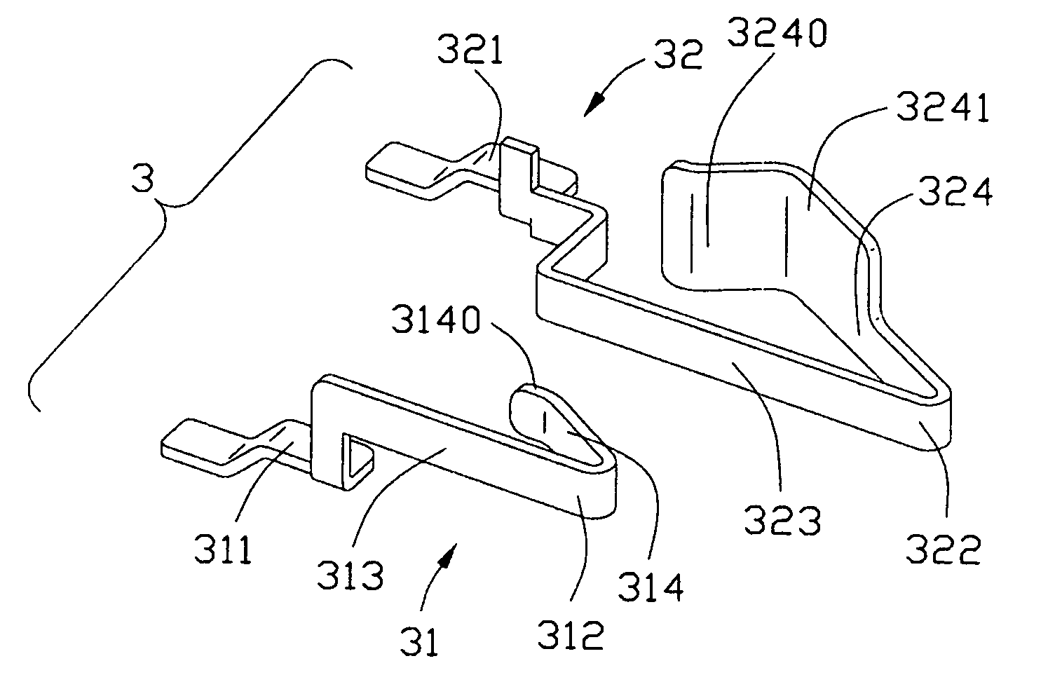
The present invention provides a card connector with an improved reliable switch for detecting the presence of an insertion card. The connector is robust and durable. The connector includes an insulative housing with a card receiving space, a plurality of contacts retained in the housing for electrically connecting with the card, and first and second spring switch contacts located on the insulative housing to be directly actuated by the card in direct response to insertion. The first and second spring switch contacts have deflectable body portions with connecting legs and free legs that can actuate each other when the card is inserted. The presence or absence of the card can be detected directly by the electrical switch and the circuit traces on the external circuit board.

Problems solved by technology

However, in the above structure of the detector switch used in the conventional card connector, the movable switch terminal is easily to be intolerant and out of condition after being repeated deflected by the inserted card.
When the card is of negative dimension tolerance, the movable contact of the switch may not get sufficient pressing force from the inserted card, resulting in an unreliable connection between the movable contact and the unmovable contact and rendering the switch inoperative.
When the card is of positive dimension tolerance, the movable contact of the switch may accept excessive pressing force from the inserted card and easily to be damaged, resulting in a short life-span thereof.
Although this design is used in many applications, there is broadly space for improving.

Method used


Image

  • Card connector having switch contacts
  • Card connector having switch contacts
  • Card connector having switch contacts

Examples


Embodiment Construction

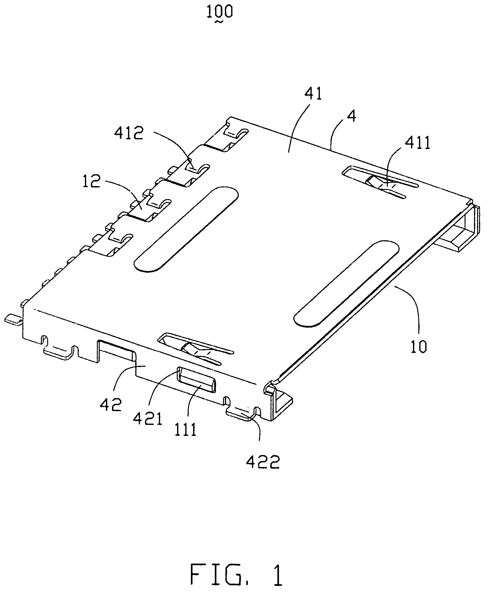
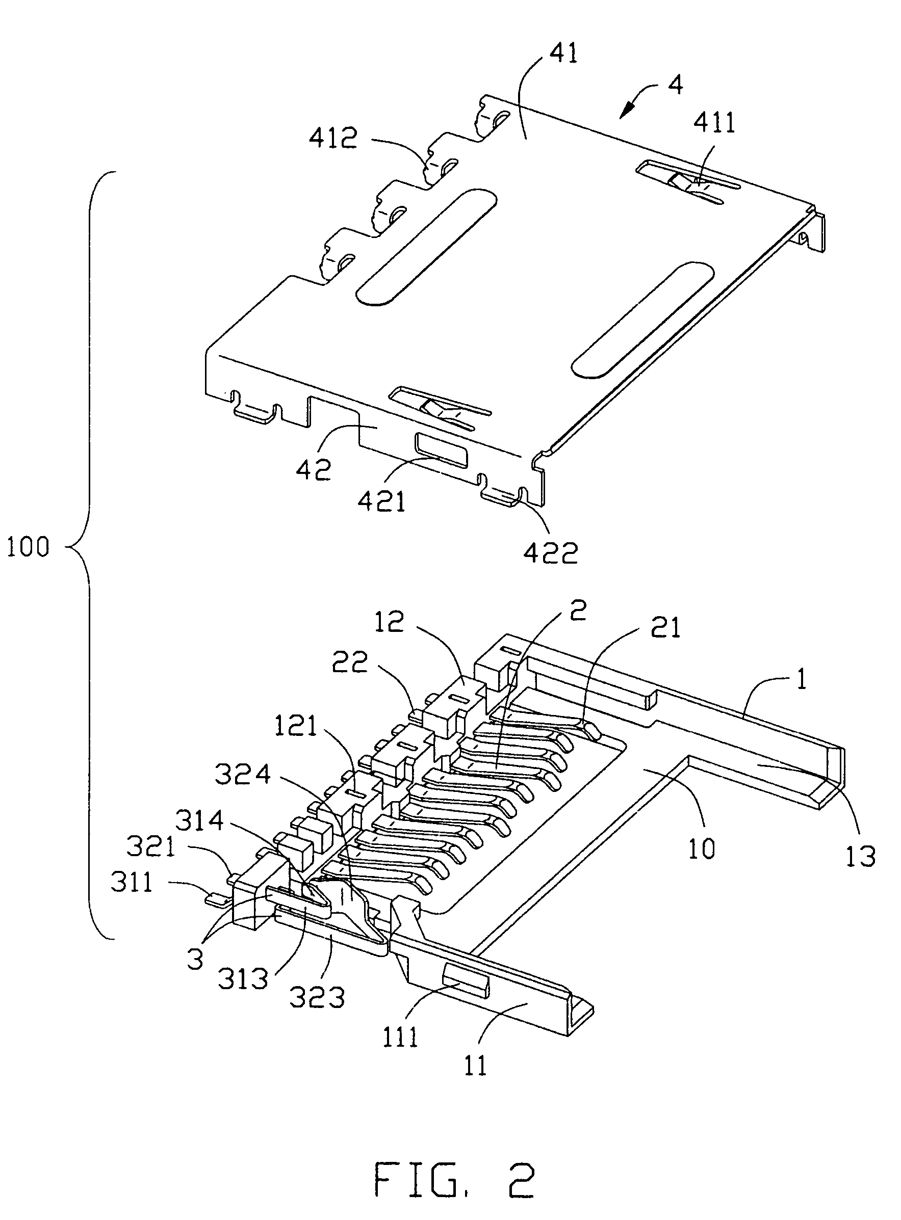
[0020]The present invention will now be described with reference to drawings, and first to FIGS. 1 and 2. A card connector 100 according to the present invention is provided for interconnection between a card (not shown), such as a memory card, and a circuit board (not shown). The card connector 100 includes an insulative housing 1, a plurality of conductive terminals 2 mounted on the housing 1 adapted for electrically connecting with the card, an electrical switch 3 for detecting the presence or absence of the card, and an outer shell 4 substantially covering the housing 1.

[0021]As best shown in FIGS. 2 and 3, the insulative housing 1 comprises a base plate 13 and a U-shaped peripheral frame (not labeled) substantially surrounding the base plate 13. The U-shaped peripheral frame includes a rear rim 12 and a pair of side rims 11 interconnecting end-to-end and upwardly extending form the respective left, right and rear sides of the base plate 13. Thus, a card receiving space 10 is de...


PUM


Abstract

A card connector (100) provided for interconnecting the card to an external circuit board includes an insulative housing (1), a number of terminals (2) retained in the housing for electrically connecting with the card, and first and second spring switch contacts (31, 32). The first and second spring switch contact respectively include a first and second lead (311, 312) secured in the housing and extending outwardly for electrical connection with an external circuit board, and a generally U-shaped first and second deflectable body portion (312, 322). The first deflectable body portion has a first free leg (314) defining a first spring contact portion (3140). The second deflectable body portion has a second free leg (324) having a deflecting portion (3241) adapted to be actuated by the card in direct response to insertion thereof and a second spring contact portion (3240) adapted for engaging with said first spring contact portion.

Description

BACKGROUND OF THE INVENTION[0001]1. Filed of the Invention[0002]The present invention relates to a card connector, and more particularly to a card connector capable of reliably holding an inserted card.[0003]2. Description of the Prior Art[0004]Known IC cards have memory and / or an IC for serving as a control circuit. By loading such an IC card into electronic apparatuses such as cellular phones, telephones, PDAs, cameras and the like, functions of these electronic apparatuses can be enhanced. Examples of such IC cards include memory cards such as Subscriber Identity Module Card (SIM card), Multi Media Card (MMC), Smart Media, Secure Digital Card (SD card), Memory Stick, and Compact Flash Card.[0005]Card connectors are provided for connecting such cards to circuit boards of the electronic devices. Switches have been designed into such conventional card connectors for the purpose of detecting the presence of inserted cards. See, for example, U.S. Pat. No. 5,511,986. Generally a switch...

Claims


Application Information

Patent Timeline
Patent Type & Authority Patents(United States)
IPC IPC(8): G06K7/06H01R13/629
CPCH01R13/7031G06K7/003
Inventor YANG, MENG HUANSU, TIEN-CHIEH
Owner HON HAI PRECISION IND CO LTD
Learn More