Harness for a handheld power equipment

a power equipment and harness technology, applied in the field of harnesses, can solve the problems of not fitting the user's back, affecting the use of the harness,

Inactive Publication Date: 2015-01-06
MAKITA CORP
View PDF61 Cites 24 Cited by
  • Summary
  • Abstract
  • Description
  • Claims
  • Application Information

AI Technical Summary

Benefits of technology

[0007]With the conventional harness, the protector plate arranged between the user and the equipment may absorb the vibration and shock transmitted from the equipment to the user to a certain degree. However, the vibration and shock transmitted from the equipment to the user cannot be sufficiently inhibited by simply arranging the protector plate between the user and the equipment. Accordingly, the conventional harness is provided with a pad arranged on the rear surface of the protector plate that comes into contact with the user, which reduces the vibration and shock transmitted from the equipment to the user. According to this construction, although certain effects will be obtained, the construction of the protector plate is complicated.
[0008]It is an object of the present teachings to disclose a technique for improving at least one of the problems with the conventional harness, and provide a novel and useful harness. For example, teachings for reducing the discomfort felt by the user due to contact with the backplate may be provided. Alternatively, teachings for conforming the shape of the backplate to the shape of the user's back and thus improve the fit of the backplate may be provided. Alternatively, teachings for reducing the load on the shoulders of the user caused by the weight of the handheld power equipment may be provided. Alternatively, teachings for inhibiting vibration and shock transmitted from the equipment to the user without adding a shock absorbing part, such as a pad, to the protector plate, may be provided.
[0010]In one embodiment of the present teachings, it is preferable that the backplate comprises at least one ventilation groove formed on an inner surface of the backplate. Here, the inner surface of the backplate means a surface of the backplate that will be in close contact with the back of the user when the backplate is arranged on the back of the user. According to this construction, ventilation between the backplate and the back of the user will be improved by the ventilation grooves formed in the inner surface of the backplate. In this configuration, it will be difficult for heat and moisture to be trapped between the backplate and the back of the user, and the sense of discomfort felt by the user due to the backplate may be reduced.
[0012]The back of the user is curved rearward in a convex shape in the height direction along the curvature of the thoracic vertebrae. Because of this, the fit of the backplate can be improved by making at least a portion of the backplate in the height direction the posteriorly-convex portion that curves rearward with respect to the user in the convex shape in the height direction. Furthermore, both side parts in the width direction of the user's back where the shoulder blade are present are more convex in the rearward direction than the middle part thereof in the width direction. Because of this, with the posteriorly-convex portion of the backplate described above, the fit of the backplate can be further improved by making both side parts in the width direction more convex than the middle part in the width direction.
[0013]In one embodiment of the present teachings, it is preferable that the harness further comprises a shoulder plate integrally-formed with the backplate and configured to be arranged on a shoulder of the user. According to this construction, the load on the shoulders of the user (the weight of the handheld power equipment) will be distributed onto the back of the user by the backplate, and thus the burden on the shoulders of the user will be reduced.
[0015]According to the construction of the protector plate described above, the equipment will come into contact with the protrusion formed on the edge of the protector plate, but will not come into contact with the middle part of the protector plate. In contrast, the user will come into contact with the middle part of the protector plate from the opposite side of the equipment. In other words, with this protector plate, the area in which the equipment will come into contact therewith is different from the area in which the user will come into contact therewith. In this configuration, the vibration and shock transmitted from the equipment to the user via the protector plate will be markedly mitigated. Furthermore, the protector plate can passively bend in response to the vibration and shock from the equipment, and can absorb that vibration and shock. In other words, the protector plate functions as a plate spring. According to this protector plate, vibration and shock transmitted from the equipment to the user can be inhibited without adding a shock absorbing component such as a pad.

Problems solved by technology

With the conventional harness, the inner surface of the backplate is in close contact with the user's back, and thus heat and moisture is trapped between the backplate and the user's back, which consequently may disturb the user with a sense of discomfort.
With the conventional harness, there are problems in that the backplate has a flat shape, the backplate does not fit the user's back, and the harness cannot stably support the handheld power equipment.
Thus, there is a problem in that the burden on the shoulders of the user is extremely large.
However, the vibration and shock transmitted from the equipment to the user cannot be sufficiently inhibited by simply arranging the protector plate between the user and the equipment.
According to this construction, although certain effects will be obtained, the construction of the protector plate is complicated.

Method used


Image

  • Harness for a handheld power equipment
  • Harness for a handheld power equipment
  • Harness for a handheld power equipment

Examples


embodiment 1

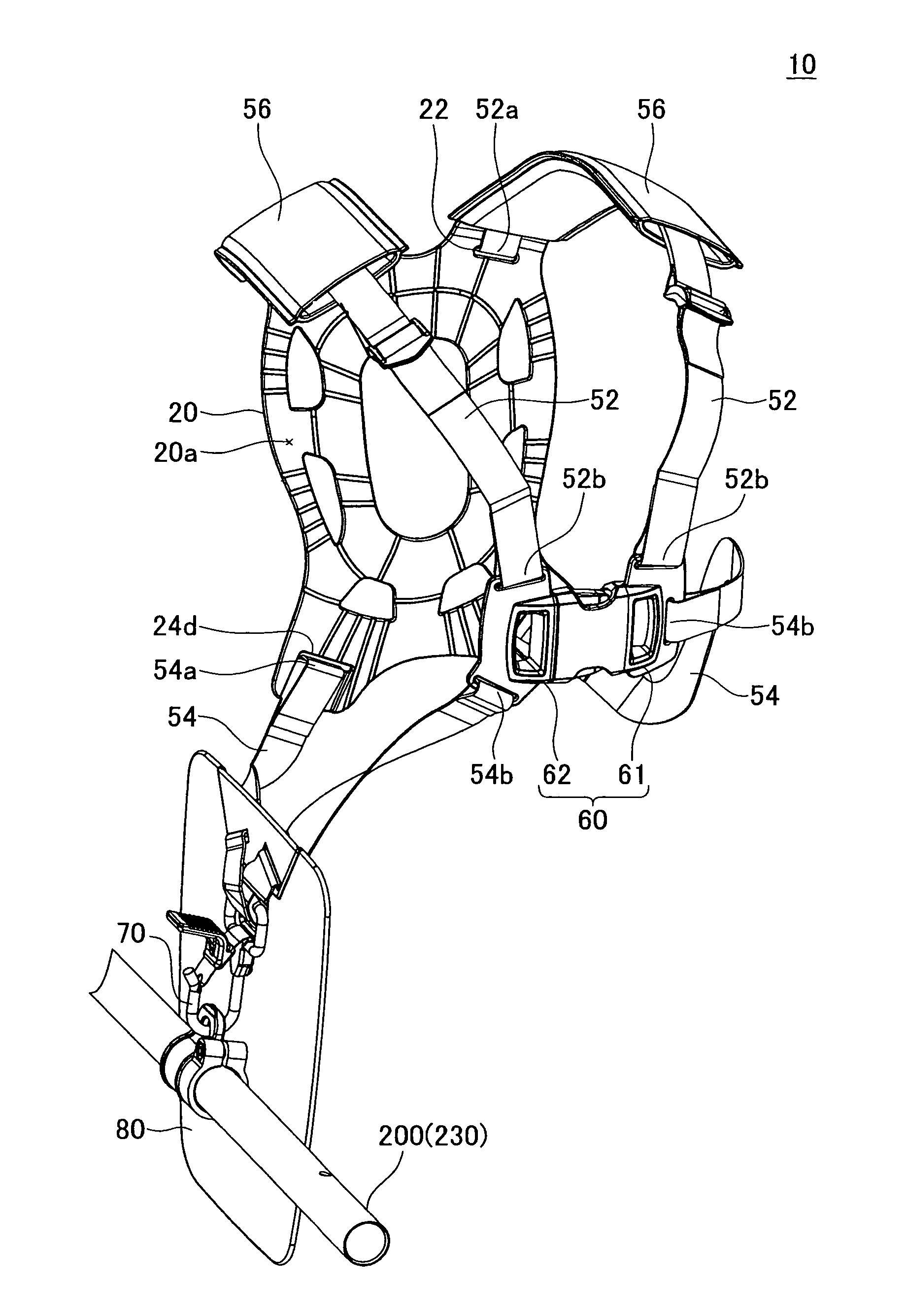
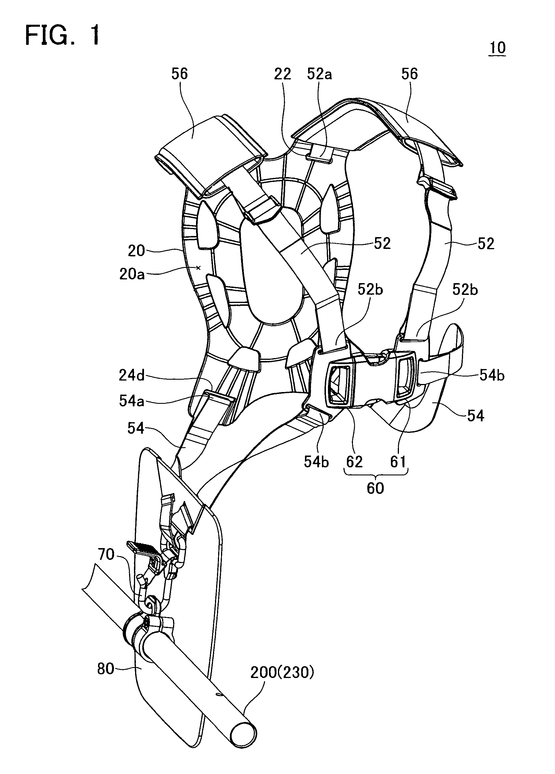
[0061]A harness 10 of Embodiment 1 will be described with reference to the drawings. FIG. 1 and FIG. 2 are perspective views showing the entire harness 10. The harness 10 is a mounting tool worn by the user in order to support a handheld power equipment such as a brush cutter 200 (see FIG. 15) or a blower.

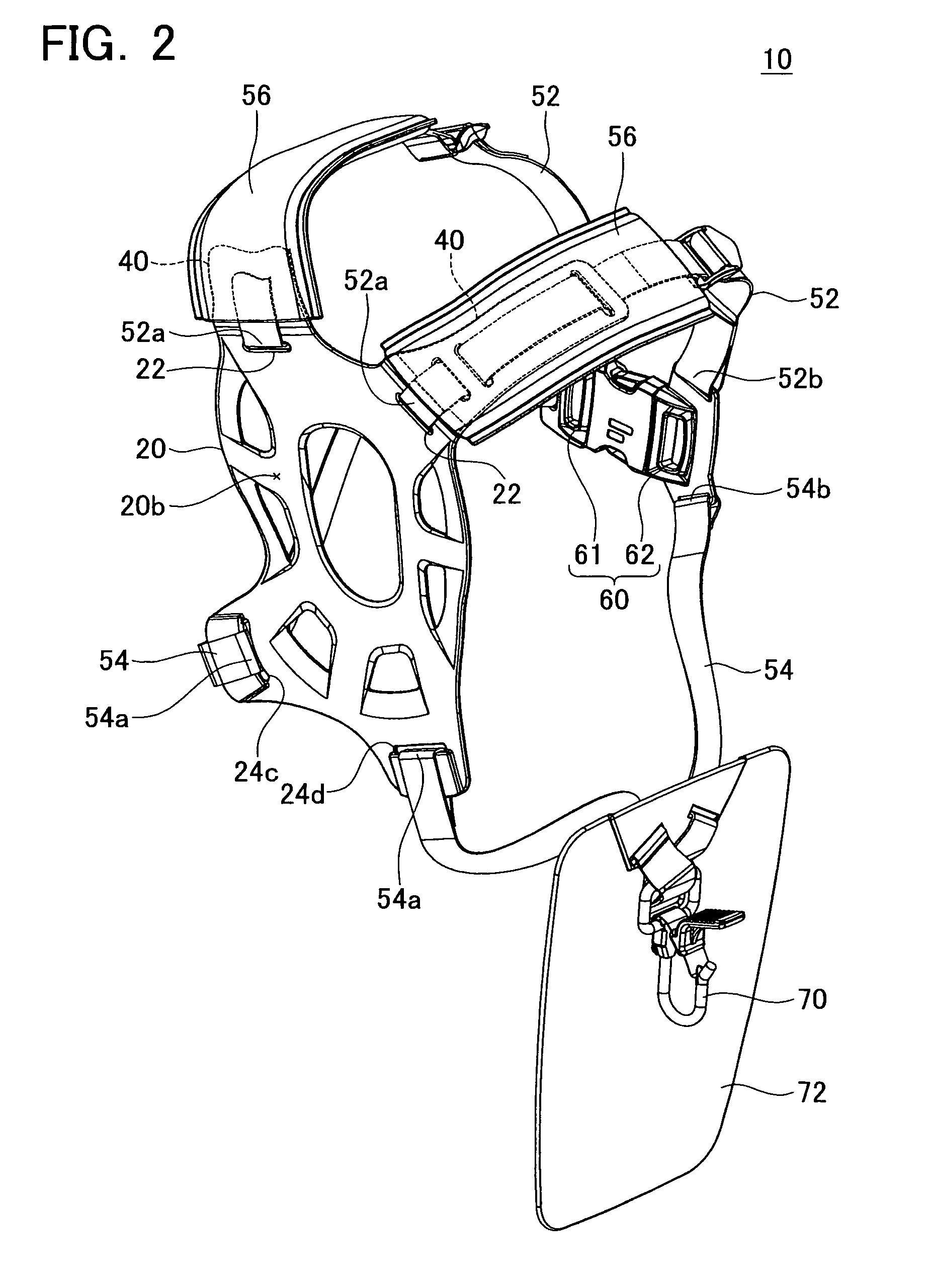
[0062]As shown in FIG. 1 and FIG. 2, the harness 10 comprises a backplate 20. The backplate 20 is arranged on the back of the user (not shown in the drawings) when the user wears the harness 10. At this point, an inner surface 20a of the backplate 20 shown in FIG. 1 faces the back of the user, and an outer surface 20b of the backplate 20 shown in FIG. 2 is exposed rearward on the back of the user.

[0063]A pair of shoulder plates 40 is formed on the backplate 20. The pair of shoulder plates 40 extends from the upper portion of the backplate 20. The shoulder plates 40 are respectively arranged on both shoulders of the user when the user wears the harness 10. The shoulder plates 40 are...

embodiment 2

[0096]A harness 110 of Embodiment 2 will be described with reference to the drawings. FIG. 14 is a perspective view showing the entire harness 110. The harness 110 is a mounting tool worn by the user, and serves to hold the brush cutter 200 shown in FIG. 15. Note that FIG. 2 shows an example of the brush cutter 200, and usage of the harness 110 is not limited to the brush cutter 200 shown in FIG. 15. Furthermore, the harness 110 is not limited to the brush cutter 200, and for example can also be used with other types of handheld power equipment such as a blower.

[0097]Compared to the harness 10 of Embodiment 1, the shape of a protector plate 180 is changed on the harness 110 of Embodiment 2. In contrast, with regard to the other construction of the backplate 20 etc., the harness 110 is substantially the same as the harness 10 of Embodiment 1. Thus, the shape, characteristics, and function of the protector plate 180 will be described in detail, but with regard to the other constructio...


PUM


Abstract

The harness comprises a backplate, a plurality of belts and an attachment. The backplate is arranged on the back of the user. The plurality of belts is configured so that one end of each belt is connected to the backplate and another end of each belt is connected to each other on the front of the user. The attachment is supported by at least one of the backplate and the plurality of belts, and is configured to be attached to the power equipment. The backplate preferably comprises at least one ventilation groove formed on its inner surface and extending to the edge of the backplate, which allows air to pass between the user and backplate easily.

Description

CROSS-REFERENCE TO RELATED APPLICATIONS[0001]This application claims priority to (1) Japanese Patent Application No. 2009-106327 filed on Apr. 24, 2009, (2) Japanese Patent Application No. 2009-106328 filed on Apr. 24, 2009, (3) Japanese Patent Application No. 2009-106329 filed on Apr. 24, 2009, and (4) Japanese Patent Application No. 2009-280096 filed on Dec. 10, 2009, the contents of which are hereby incorporated by reference into the present application.TECHNICAL FIELD[0002]The present invention relates to a harness that is worn by a user in order to support a handheld power equipment.DESCRIPTION OF RELATED ART[0003]A harness that is worn by a user in order to support a handheld power equipment, such as a brush cutter or a blower, is disclosed in Japanese Patent Application Publication No. 2005-143453 A. This harness comprises a backplate configured to be arranged on a back of the user, a plurality of belts that are connected to the backplate, an attachment configured to be attac...

Claims


Application Information

Patent Timeline
Patent Type & Authority Patents(United States)
IPC IPC(8): A45F3/08A45F3/04A45F3/14A01D34/90A45F3/12
CPCA45F3/14A01D34/902A45F2003/125A45F2003/146
Inventor MORI, RYOTAHACHISUKA, TOMOHIROITO, MASAHIRO
Owner MAKITA CORP
Why Eureka
Try Eureka