Top side coupling gauge mandrel

a top-side coupling and gauge technology, applied in the field of instrumented couplings, can solve the problems of increasing the risk of having to scrap carriers, and achieve the effects of reducing the total amount of material required for couplings (carriers and sensor packages), reducing cost, and reducing cos

Pending Publication Date: 2022-06-16
BAKER HUGHES OILFIELD OPERATIONS LLC
View PDF6 Cites 0 Cited by
  • Summary
  • Abstract
  • Description
  • Claims
  • Application Information

AI Technical Summary

Benefits of technology

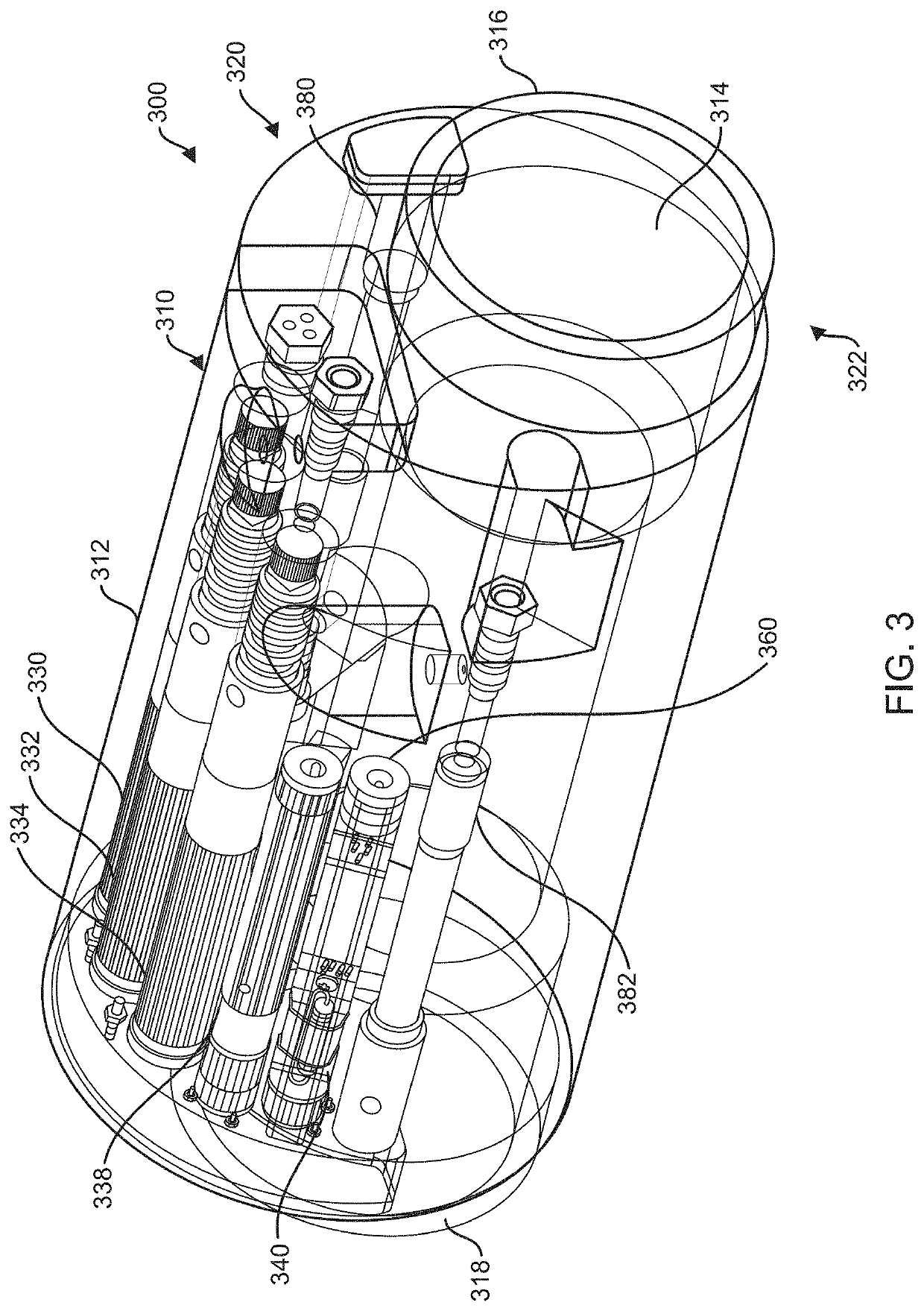
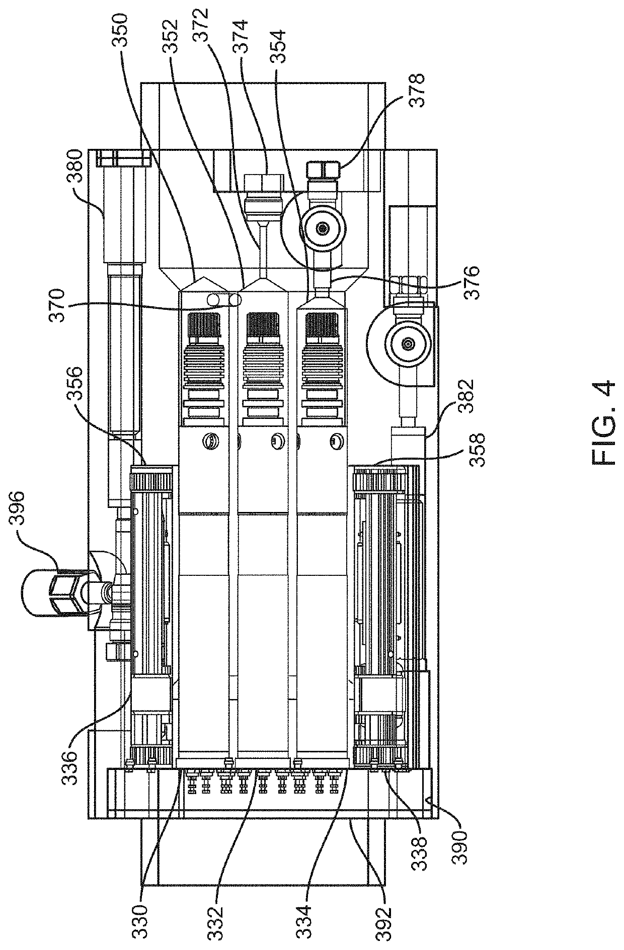
[0009]One embodiment comprises an instrumented downhole coupling that includes a carrier and a set of sensors and electronics that are installed within the carrier. The carrier is a tubular structure having a first coupling at a first end and a second coupling at the opposite end. A bore extends through the carrier from the first end to the second end, forming a carrier wall between the bore and the exterior surface of the carrier. The bore is offset from a central axis of the carrier (the axis of the cylindrical outer surface of the carrier), creating an increased-thickness portion of the carrier wall on a first side of the carrier. A sensor cavity is formed within the increased-thickness portion of the carrier wall (e.g., by machining the cavity into the wall), where the cavity has a side opening that faces away from the central axis of the carrier. One or more sensors are positioned within the cavity and electrical connections between the sensors and corresponding electronics and / or power / communication cables are made. The sensors may include, for example, a tubing sensing gauge, an annulus sensing gauge, etc. The sensors may be secured within the cavity by a clamp that holds them in position. After the sensors are secured in the cavity, protective plates are welded into place over the side-facing opening to seal the opening. This forms a sealed enclosure around the sensors in the cavity, except that the cavities may be in fluid communication with the bore of the coupling or the annulus between the coupling and the well bore. The coupling thereby prevents fluids at the bore and the exterior of the carrier from reaching the cavities containing the sensors and the electronics packages.
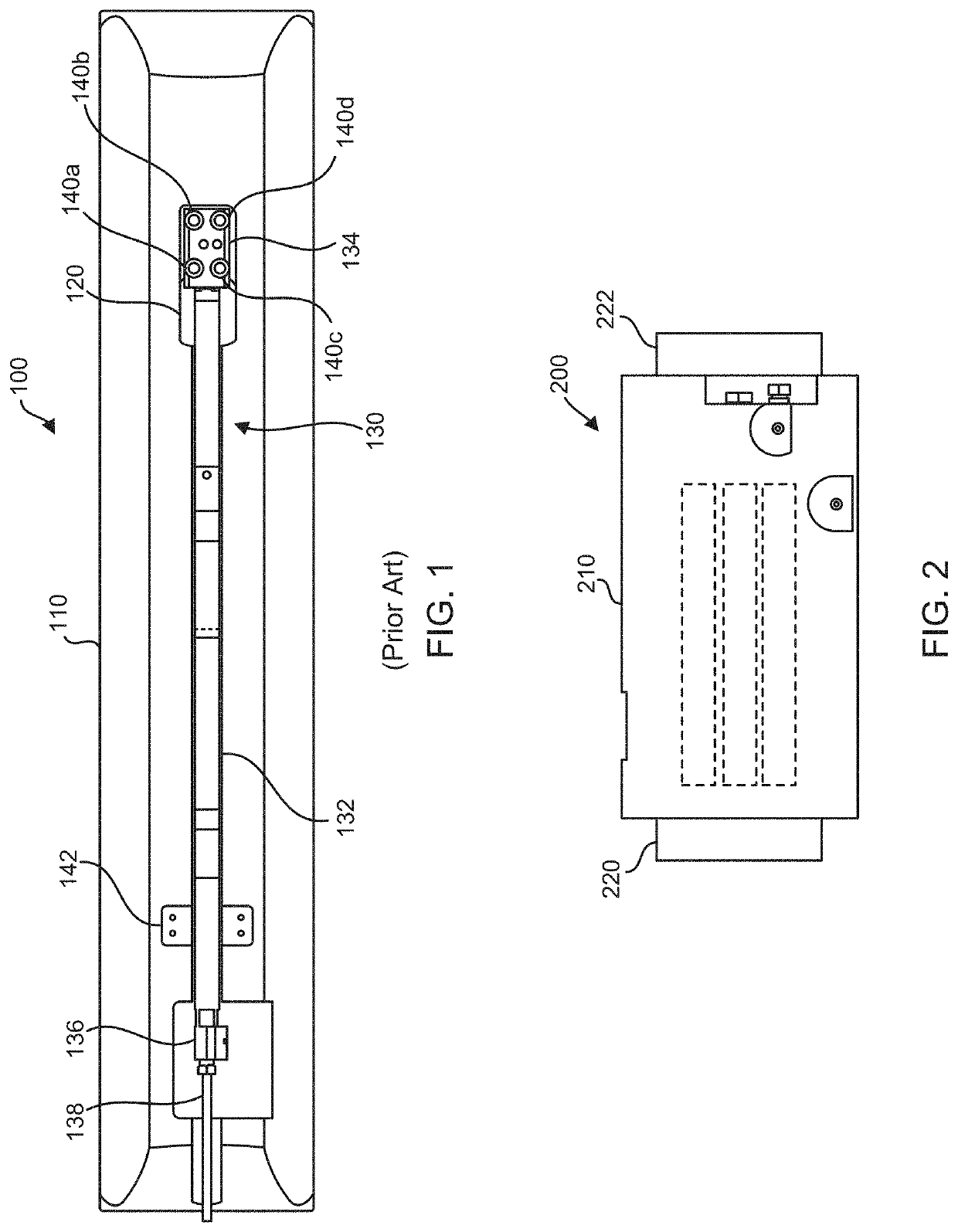
[0010]The cavity within the carrier wall may be sized to accommodate one or more sensors positioned at circumferentially displaced locations around the carrier, typically with the elongated sensors side-by-side within the carrier wall. The carrier may therefore be shorter than a conventional carrier in which the components of each sensor assembly (e.g., sensor, electronics, manifold) are positioned end-to-end in a tubular housing (see FIG. 1, discussed below). Since the carrier itself serves as the sensor housing, the material of the conventional sensor housing can be eliminated, and the overall amount of material which is required for the coupling (carrier and sensor packages) is reduced. In relation to existing carriers having gun drilled cavities, the size and amount of material used is comparable, but the present embodiments can be manufactured at significantly less cost. The reduced cost may result from a number of different factors, such as the elimination of gun drilling, which is a costly process and increases the risk of having to scrap carriers due to problems during their manufacture. Since the sensor cavities in the present embodiments are open to the side and are open along the entire length of the cavities, there is much greater access to the sensors in the cavities for installation, soldering and splicing of wires, which reduces the time and labor required to manufacture the couplings. Further, the open side access to the cavities enables the use of a clamp to secure the sensors in the cavities, which reduces the vibration and shock to the sensors and increases their reliability. Still further, the weld profiles on the present embodiments are less complicated than those for previous carriers having gun drilled cavities, which reduces the time and labor requirements.

Problems solved by technology

The reduced cost may result from a number of different factors, such as the elimination of gun drilling, which is a costly process and increases the risk of having to scrap carriers due to problems during their manufacture.

Method used


Image

  • Top side coupling gauge mandrel
  • Top side coupling gauge mandrel
  • Top side coupling gauge mandrel

Examples


Embodiment Construction

[0029]One or more embodiments of the invention are described below. It should be noted that these and any other embodiments described below are exemplary and are intended to be illustrative of the invention rather than limiting.

[0030]This disclosure is directed to an improved instrumented coupling or gauge package that uses a carrier which serves as a housing for sensors and associated electronics that are installed in pockets or cavities within the carrier wall. The carrier may have an offset bore, so that the carrier wall is thicker on one side, allowing larger cavities to be provided for the sensors and electronics.

[0031]Referring to FIGS. 1 and 2, diagrams illustrating differences between a conventional gauge package and a gauge package (an instrumented coupling) having gun drilled cavities are shown. As depicted in FIG. 1, the conventional gauge package 100 is constructed using an elongated tubular mandrel 110 which serves as a carrier. A coupling is formed at each end of the m...


PUM


Abstract

A compact instrumented downhole coupling that includes a carrier and a set of sensors and electronics that are installed within the carrier. The carrier is a tubular structure having couplings at each end and a bore therethrough, where cavities are formed in the carrier wall. The cavities are open to a side facing away from the carrier's bore, where sensors placed in the cavities are accessible through the side opening. Electrical connections to the sensors are made via the side opening, and a clamp can be installed in the cavities via the side opening, the clamp holding the sensors securely in position within the cavities. After installation of the sensors in the cavities, plates are welded over the side opening to form an enclosure for the sensors in the carrier wall.

Description

RELATED APPLICATIONS[0001]This application is a continuation-in-part of and claims priority to U.S. patent application Ser. No. 17 / 124,400, entitled “Instrumented Coupling Electronics”, filed Dec. 16, 2020, which is fully incorporated herein by reference for all purposes.BACKGROUNDField of the Invention[0002]The invention relates generally to electronic equipment, and more particularly to instrumented couplings that are configured to be installed downhole in wells.Related Art[0003]It is often desirable to use electronic sensors to make measurements of conditions within a well. These sensors may be installed on in-line carriers that are connected to production tubing or other pieces of downhole equipment that are positioned within the well. Traditionally, the carriers are constructed by forming a mandrel that has couplings on each end and a bore therethrough so that it can be connected in line with the tubing and / or equipment. A single narrow groove is milled into the exterior surfac...

Claims


Application Information

Patent Timeline
Patent Type & Authority Applications(United States)
IPC IPC(8): E21B47/12E21B47/017
CPCE21B47/12E21B47/017E21B47/01E21B47/013E21B47/06E21B17/00
Inventor LOH, YUHRAGGIO, JOHNRENDALL, LORN
Owner BAKER HUGHES OILFIELD OPERATIONS LLC
Why Eureka
Try Eureka