Pneumostoma management device with integrated patency sensor and method

Inactive Publication Date: 2010-07-08
PORTAERO
View PDF104 Cites 26 Cited by
  • Summary
  • Abstract
  • Description
  • Claims
  • Application Information

AI Technical Summary

Benefits of technology

[0031]In view of the disadvantages of the state of the art, Applicants have developed a method for treating COPD in which an artificial passageway is made through the chest wall into the lung. An anastomosis is formed between the artificial passageway and the lung by pleurodesis between the visceral and parietal membranes surrounding the passageway as it enters the lung. The pleurodesis creates an adhesion between the pleural membrane surrounding the passageway which prevents air from entering the pleural cavity and causing a pneumothorax (deflation of the lung due to air pressure in the pleural cavity). Pleurodesis results from a fibrotic healing response between the pleural membranes and may be localized to the vicinity of the passageway. The artificial passageway through the chest wall also becomes epithelialized. The result is a relatively stable artificial aperture through the chest wall which communicates with the parenchymal tissue of the lung.
[0032]The artificial aperture into the lung through the chest is referred to herein as a pneumostoma. The pneumostoma provides an extra pathway that allows air to exit the lung while bypassing the natural airways which have been impaired by COPD and emphysema. By providing this ventilation bypass, the

Problems solved by technology

However an additional ten million adults have evidence of impaired lung function indicating that COPD may be significantly underdiagnosed.
This increases the work of exhaling and leads to hyperinflation of the lung.
When the lungs become hyperinflated, forced expiration cannot reduce the residual volume of the lungs because the force exerted to empty the lungs collapses the small airways and blocks air from being exhaled.
With continued exposure to cigarettes or noxious particles, the disease progresses and individuals with COPD increasingly

Method used


Image

  • Pneumostoma management device with integrated patency sensor and method
  • Pneumostoma management device with integrated patency sensor and method
  • Pneumostoma management device with integrated patency sensor and method

Examples


Example

[0072]The following description is of the best modes presently contemplated for practicing various embodiments of the present invention. The description is not to be taken in a limiting sense but is made merely for the purpose of describing the general principles of the invention. The scope of the invention should be ascertained with reference to the claims. In the description of the invention that follows, like numerals or reference designators are used to refer to like parts or elements throughout. In addition, the first digit of a reference number identifies the drawing in which the reference number first appears.

Pneumostoma Formation and Anatomy

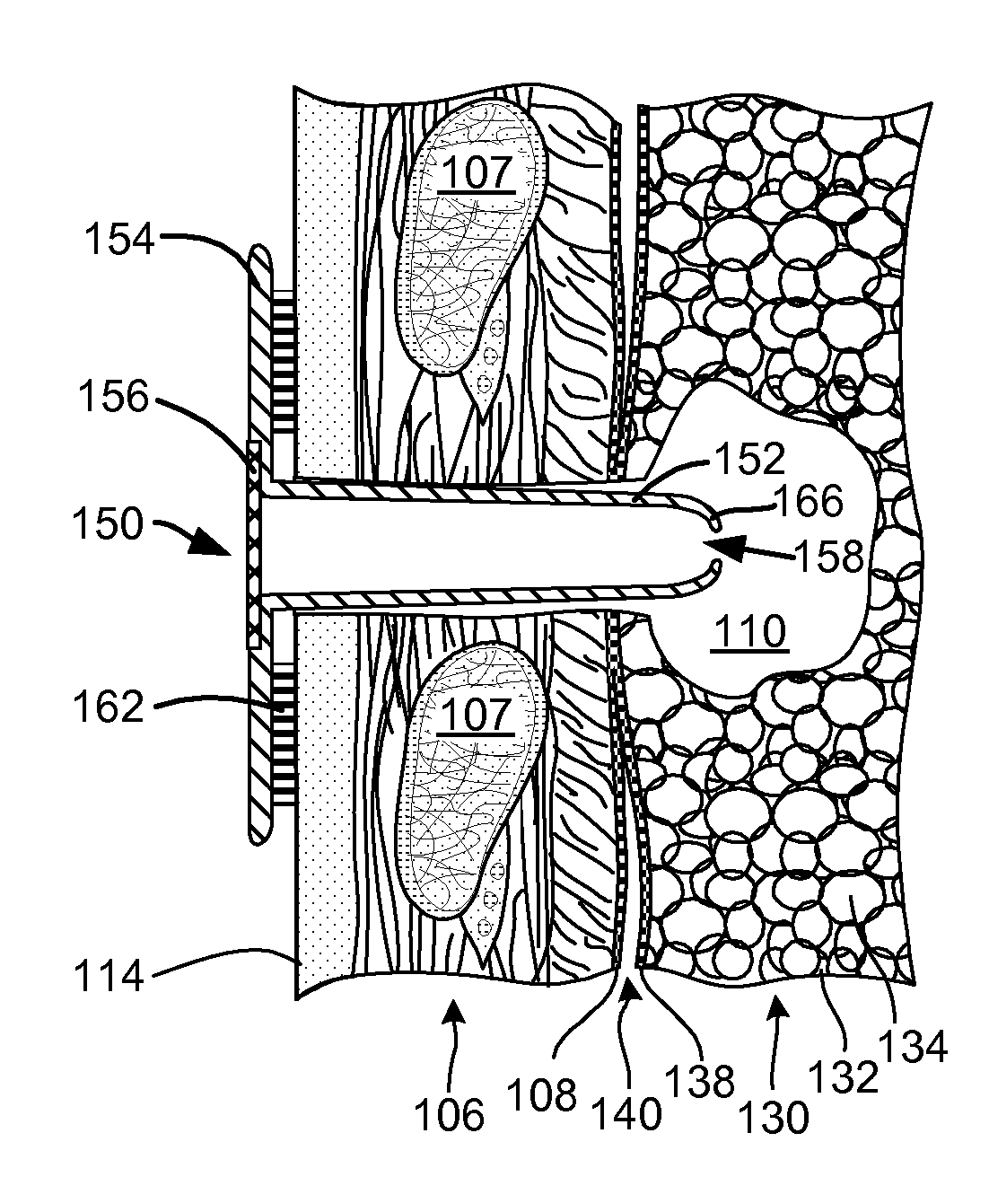
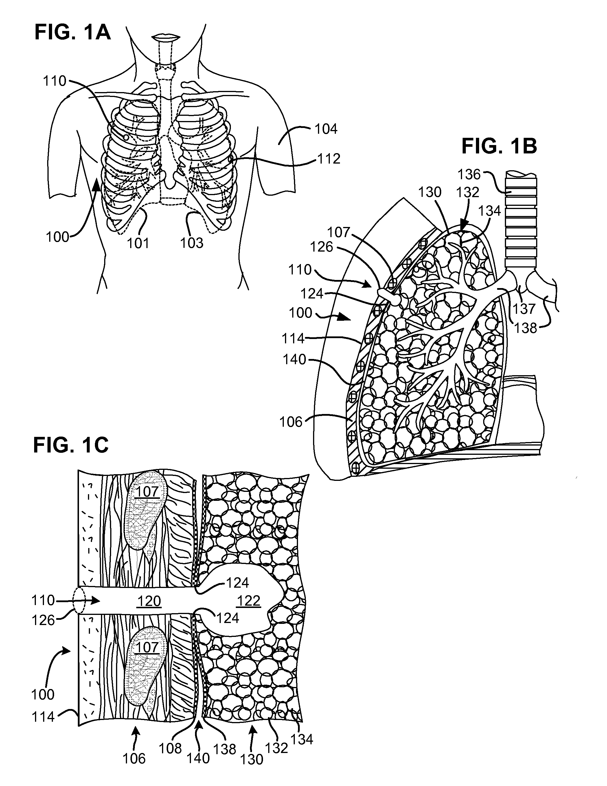
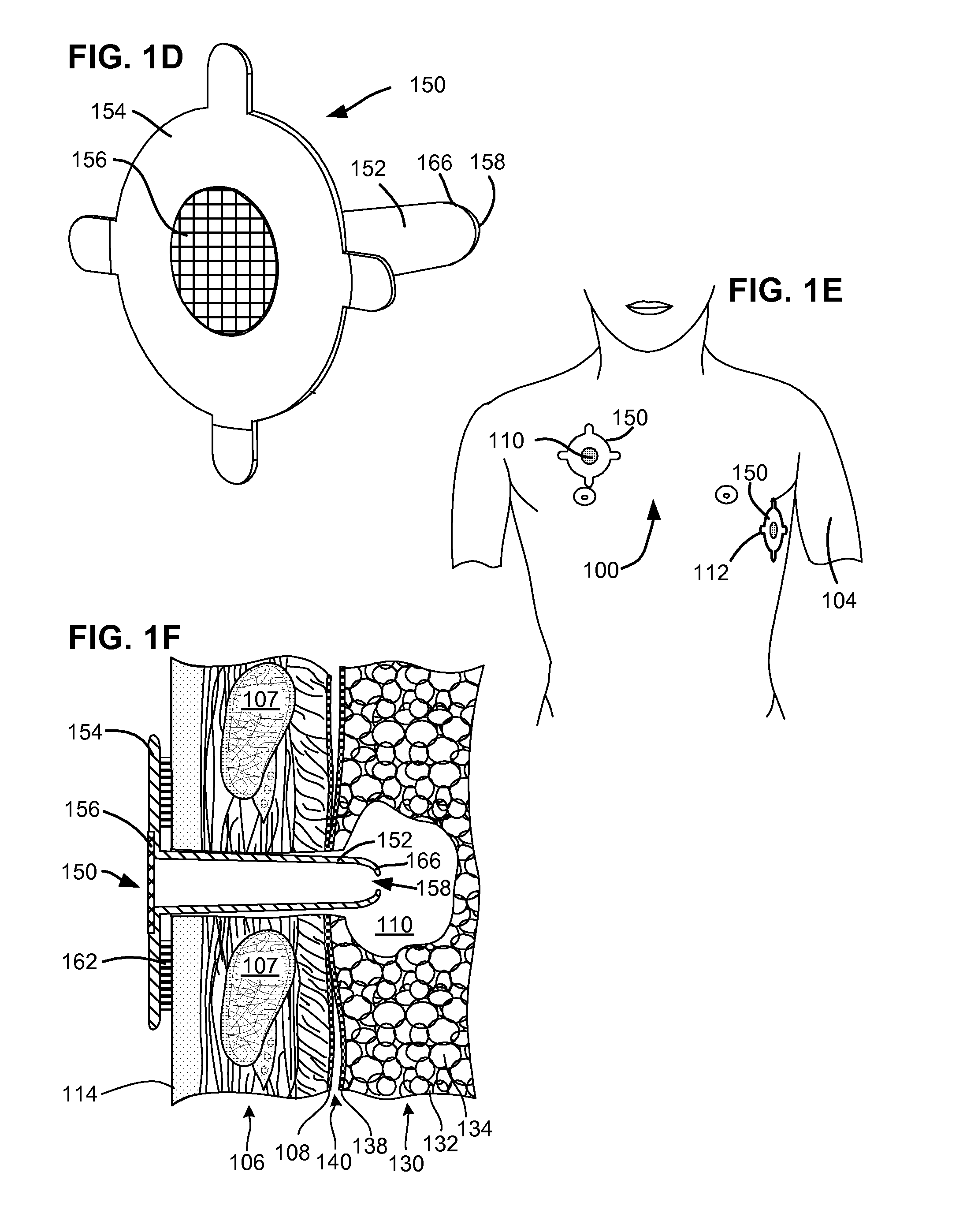
[0073]FIG. 1A shows the chest of a patient identifying alternative locations for creating a pneumostoma that may be managed using the system of the present invention. A first pneumostoma 110 is shown on the front of the chest 100 over the right lung 101 (shown in dashed lines). The pneumostoma is preferably positioned over the third inter...


PUM


Abstract

A flexible pneumostoma management device maintains the patency of a pneumostoma while controlling the flow of material through the pneumostoma. The pneumostoma management device includes a pneumostoma vent having a tube which enters the pneumostoma to allow gases to escape the lung, a flange and a filter/valve to control flow of materials through the tube. The flange is a thin flexible patch comprises of multiple thin layers of materials and which conforms and attaches to the chest of the patient. The flange includes a filter, a protective outer layer and an inner hydrocolloid layer. The flange secures the tube in position in the pneumostoma. An indicator responsive to gases exiting the pneumostoma is integrated into the device and provides and external indicia of the patency and efficacy of the pneumostoma.

Description

CLAIM TO PRIORITY[0001]This application claims priority to all of the following applications including:[0002]U.S. Provisional Application No. 61 / 143,298, filed Jan. 8, 2009, entitled “METHODS AND APPARATUS FOR THE CRYOTHERAPY CREATION OR RE-CREATION OF PNEUMOSTOMY” (Attorney Docket No. LUNG1-06006US0); and[0003]U.S. Provisional Application No. 61 / 151,581, filed Feb. 11, 2009, entitled “SURGICAL INSTRUMENTS AND PROCEDURES TO CREATE A PNEUMOSTOMA AND TREAT CHRONIC OBSTRUCTIVE PULMONARY DISEASE” (Attorney Docket No. LUNG1-06002US0).[0004]All of the afore-mentioned applications are incorporated herein by reference in their entireties.CROSS-REFERENCE TO RELATED APPLICATIONS[0005]This application is related to all of the above provisional applications and all the patent applications that claim priority thereto including:[0006]This application is related to all of the following applications including U.S. patent application Ser. No. 12 / 388,465, filed Feb. 18, 2009, entitled “ENHANCED PNEUM...

Claims


Application Information

Patent Timeline
IPC IPC(8): A61M16/00
CPCA61B5/0836A61M16/0429A61F7/007A61F7/10A61F2002/043A61F2007/0054A61M25/01A61M25/02A61M25/04A61M39/0247A61M2025/0233A61M2025/0246A61M2025/028A61M2039/0252A61M2039/0276A61M2210/1039A61N1/403A61N5/10A61N7/00A61N2005/0651A61N2005/0654A61N2005/0659A61N2005/0661A61N2005/0662A61B5/7275A61M16/0406A61M2205/7536A61B2010/0087
Inventor TANAKA, DONWIESMAN, JOSHUA P.PLOUGH, DAVID C.
Owner PORTAERO
Why Eureka
Try Eureka