Accumulator for refrigeration cycle system

a technology of accumulator and refrigeration cycle, which is applied in the field of refrigerating cycle system, can solve the problems of high cost and complicated construction of known accumulator, and achieve the effect of high cost and complicated construction

Inactive Publication Date: 2012-06-21
CALSONIC KANSEI CORP
View PDF15 Cites 7 Cited by
  • Summary
  • Abstract
  • Description
  • Claims
  • Application Information

AI Technical Summary

Benefits of technology

[0011]However, in the above-mentioned known accumulator, an electric drive mechanism is used for driving the stirring vanes 60. This means that it is necessary to provide an electric power source (or motor), a link mechanism extending between the power source and each stirring vane 60 and an electrically insulated construction for electric power transmission. Thus, the known accumulator tends to be complicated in construction and high in cost.
[0012]Accordingly, it is an object of the present invention to provide an accumulator for a refrigeration cycle system, which is free of the above-mentioned drawbacks.
[0013]That is, an object of the present invention is to provide an accumulator for a refrigeration cycle system, which can exhibit its essential function without the aid of electric power.
[0014]Another object of the present invention is to provide an accumulator for a refrigeration cycle system, which can exhibit its essential function without inducting complicated and high cost construction.
[0015]A still another object of the present invention is to provide an accumulator for a refrigeration cycle system, which can exhibit a sufficient oil circulation rate (OCR) even in a low temperature condition of an associated refrigeration cycle system.

Problems solved by technology

Thus, the known accumulator tends to be complicated in construction and high in cost.

Method used


Image

  • Accumulator for refrigeration cycle system
  • Accumulator for refrigeration cycle system
  • Accumulator for refrigeration cycle system

Examples


first embodiment

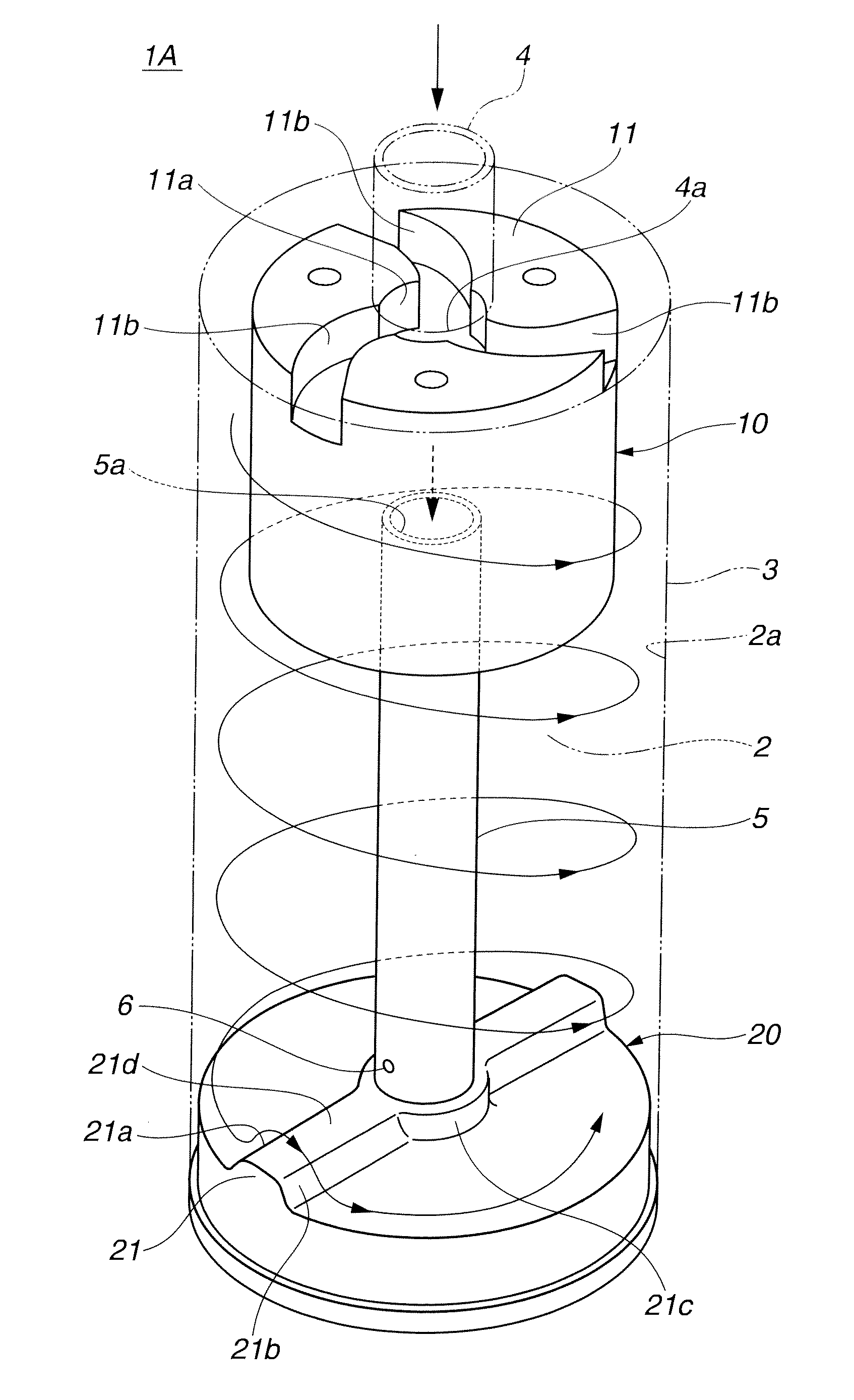
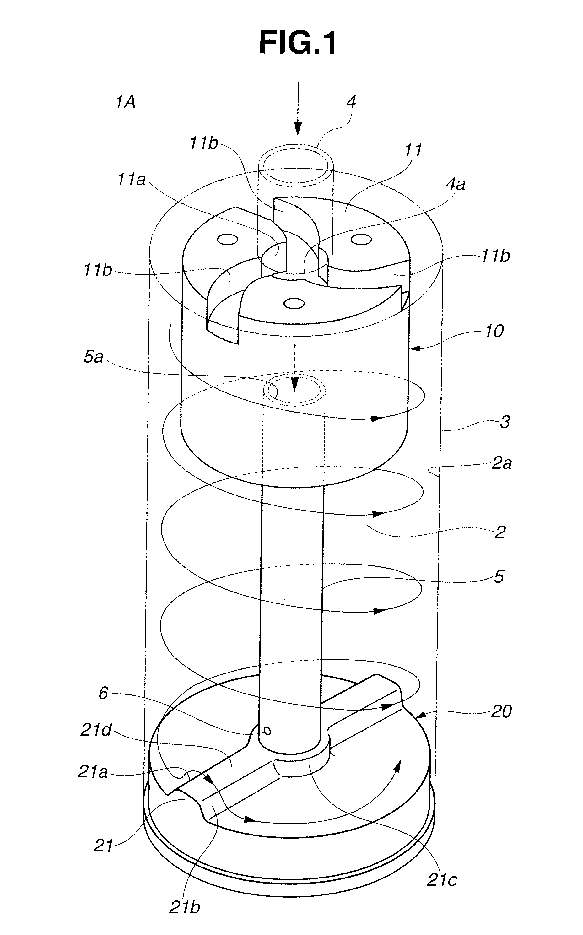
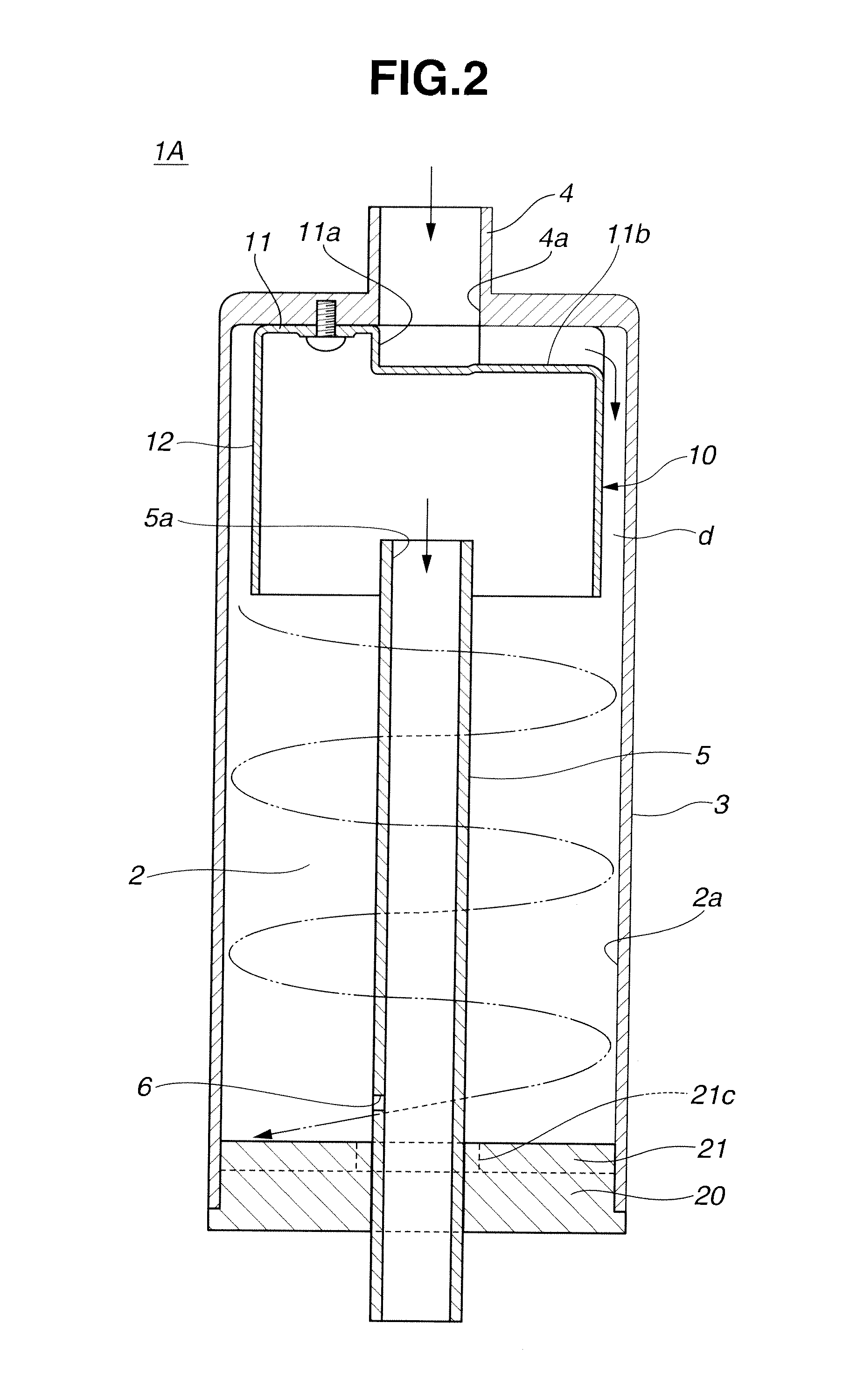
[0030]Referring to FIGS. 1 to 4, there is shown an accumulator 1A is of a first embodiment of the present invention for a refrigeration cycle system.

[0031]Like the above-mentioned known accumulator 50 of FIG. 8, the accumulator 1A of the first embodiment is arranged to stand upright when in use.

[0032]As is well shown in FIGS. 1 and 2, the accumulator 1A comprises a cylindrical case 3 that has a cylindrical liquid accumulating chamber 2 formed therein, a refrigerant inlet pipe 4 through which refrigerant is led into the liquid accumulating chamber 2 from an evaporator (not shown), a refrigerant outlet pipe 5 through which the refrigerant is discharged from the liquid accumulating chamber 2 to the outside (viz., compressor), a flow guide device 10 which provides the refrigerant from the refrigerant inlet pipe 4 with a whirling movement and an interference ridge portion 21 which provides the whirled flow of refrigerant from the flow guide device 10 with up-and-down movement (or stirs t...

second embodiment

[0058]Referring to FIGS. 5 to 7, there is shown an accumulator 1B of a second embodiment of the present invention for a refrigeration cycle system.

[0059]The accumulator 1B of the second embodiment is arranged to stand upright when in use, like in such a posture as shown in FIGS. 6 and 7.

[0060]As will be understood from FIG. 5 which is a horizontally sectrional view of the accumulator 1B, the accumulator 1B comprises a rectangular case 3 that has a rectangular liquid accumulating chamber 2 formed therein, first and second partition walls 30a and 30b that are alternately arranged in the chamber 2 to define therein first, second and third flow passages 2a, 2b and 2c that are connected in series in zigzag manner, a refrigerant inlet pipe 4 through which refrigerant is led into an upstream part of the first flow passage 2a, a refrigerant outlet pipe 5 through which the refrigerant is discharged from a downstream part of the third flow passage 2c to the outside, and a plurality of flow gu...


PUM


Abstract

An accumulator including a liquid accumulating chamber for accumulating refrigerant, a refrigerant inlet port leading the refrigerant, a refrigerant outlet pipe, an oil return opening, a refrigerant flow generating structure and a refrigerant flow mixing structure. The refrigerant outlet pipe includes an upstream open end exposed to an upper part of the liquid accumulating chamber to discharge the refrigerant from the chamber to outside the chamber. The oil return opening is in the refrigerant outlet pipe to return oil contained in the lower part of the liquid accumulating chamber to a compressor of the refrigeration cycle system. The refrigerant flow generating structure provides refrigerant from the refrigerant inlet port with a given flow, the given flow being produced by a drive force possessed by the refrigerant. The refrigerant flow mixing structure provides the given flow with an upward-and-downward movement to mix the refrigerant.

Description

BACKGROUND OF THE INVENTION[0001]1. Field of the Invention[0002]The present invention relates in general to a refrigeration cycle system and more particularly to an accumulator installed in the refrigeration cycle system at a position between an evaporator and a compressor.[0003]2. Description of the Related Art[0004]In a refrigeration cycle system of vapor-compression type (or heat pump type), there is arranged an accumulator in a refrigerant flow line at a position between an evaporator and a compressor. The accumulator has basically two functions, one being to feed the compressor with gaseous refrigerant to prevent the compressor from effecting compression against liquid refrigerant, and the other being to return oil, which circulates in the refrigeration cycle circuit together with the refrigerant, to the compressor. Actually, the oil is applied to the compressor for lubricating rotating parts of the compressor. However, under operation of the refrigeration cycle system, the oil...

Claims


Application Information

Patent Timeline
Patent Type & Authority Applications(United States)
IPC IPC(8): F25B41/00
CPCF25B2400/02F25B43/006
Inventor KAMIYAMA, NAOHISAKAWAMURA, TAKEHARU
Owner CALSONIC KANSEI CORP
Why Eureka
Try Eureka