
Hinge

a technology of hinges and hinges, applied in the field of hinges, can solve the problems of troublesome mounting of stop pieces to the shaft, complicated construction,

Inactive Publication Date: 2010-02-04
HON HAI PRECISION IND CO LTD
View PDF7 Cites 8 Cited by
  • Summary
  • Abstract
  • Description
  • Claims
  • Application Information

AI Technical Summary

Benefits of technology

[0006]For protecting the collapsible device from damage caused by excessive rotation of the hinge, the hinge is usually equipped with two stop pieces to limit a rotating angle of the hinge. Each of the stop pieces includes a stop block. The stop pieces are retained around a shaft, and are capable of rotating about each other. One of the blocks is capable of being blocked by the other of the blocks, to limit the rotating angle between the stop pieces. However, the two stop pieces usually have complicated construction, and mounting the stop pieces to the shaft is troublesome.

Problems solved by technology

However, the two stop pieces usually have complicated construction, and mounting the stop pieces to the shaft is troublesome.

Method used


Image

  • Hinge
  • Hinge
  • Hinge

Examples


Embodiment Construction

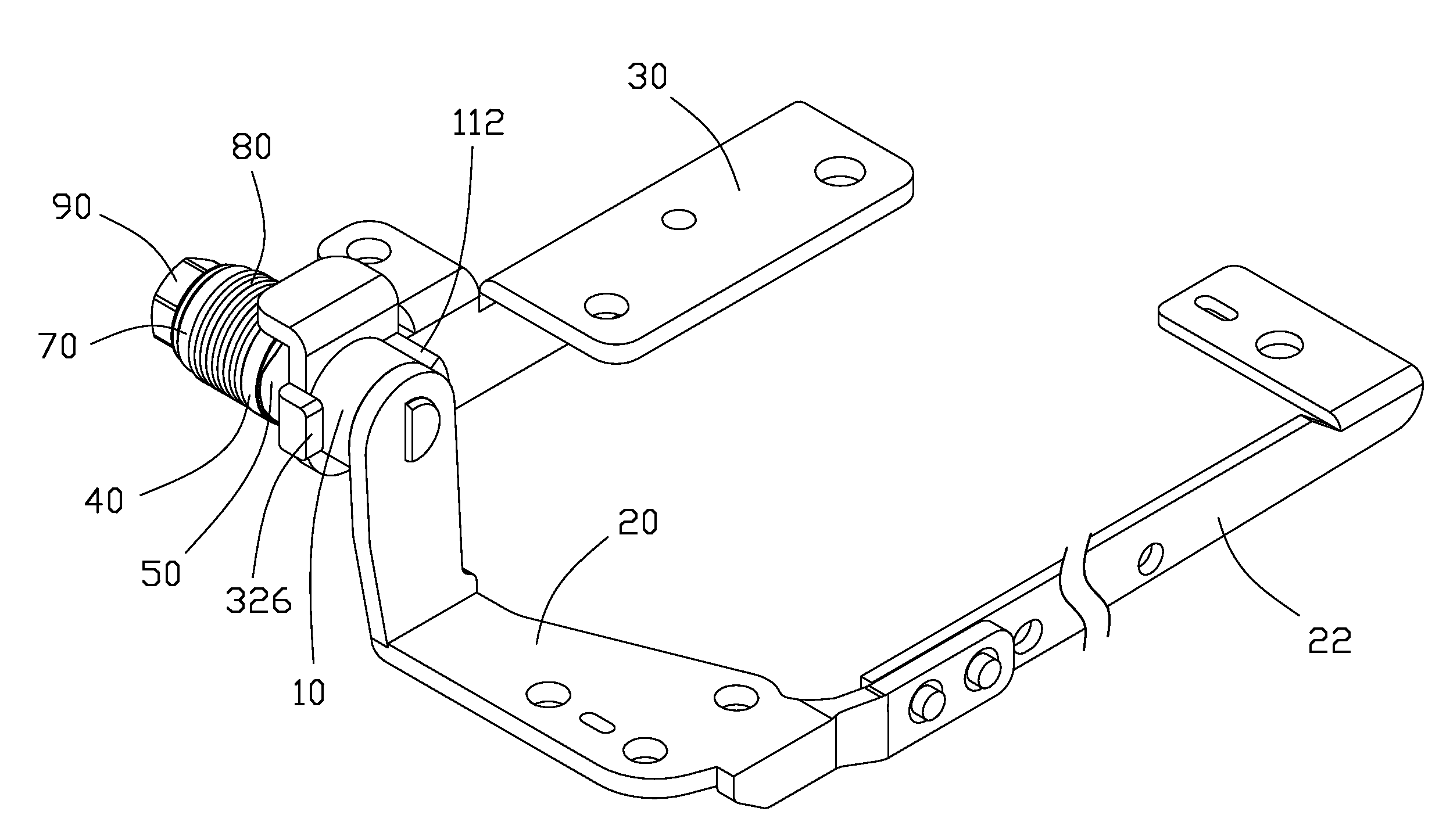
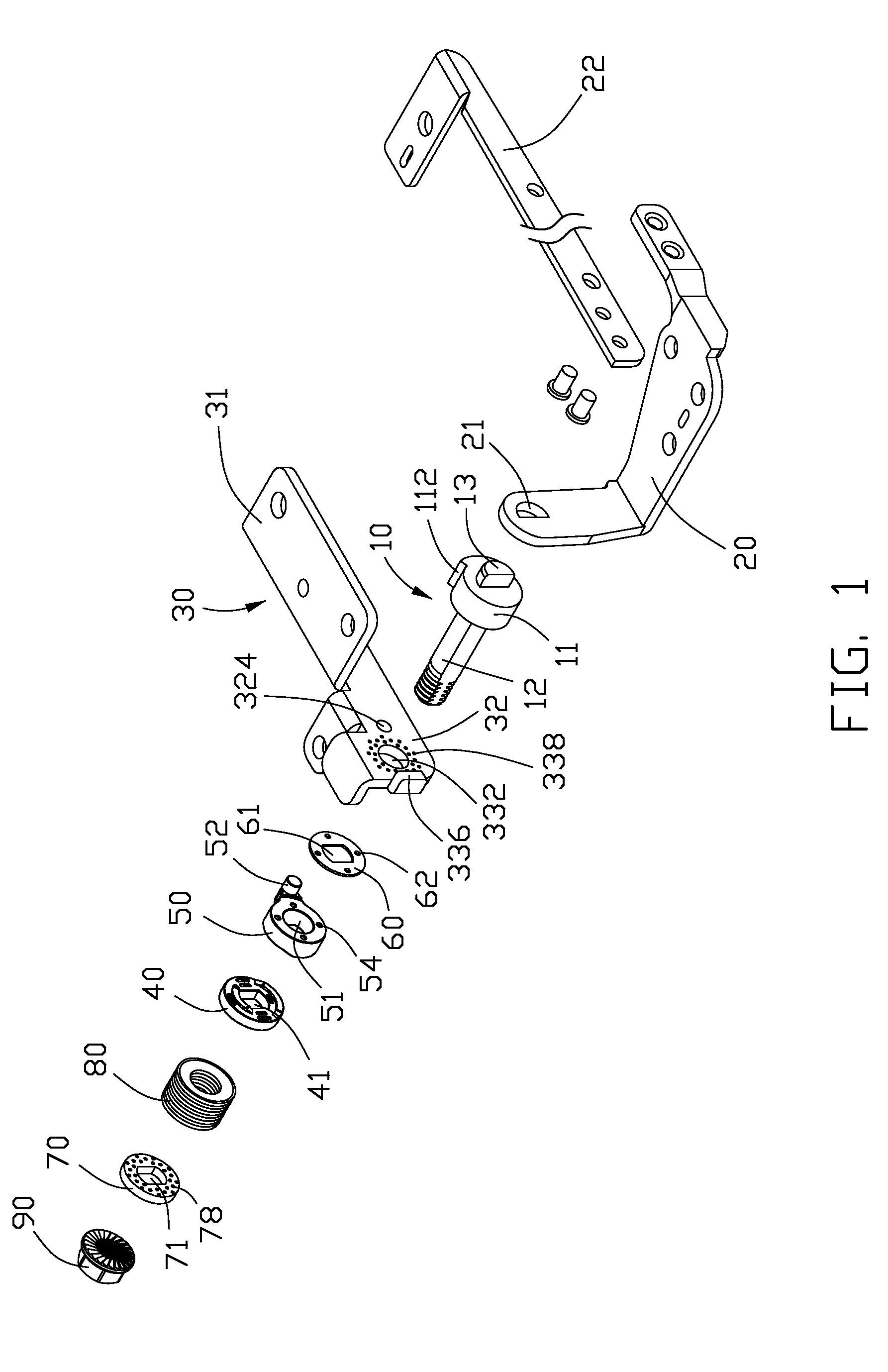
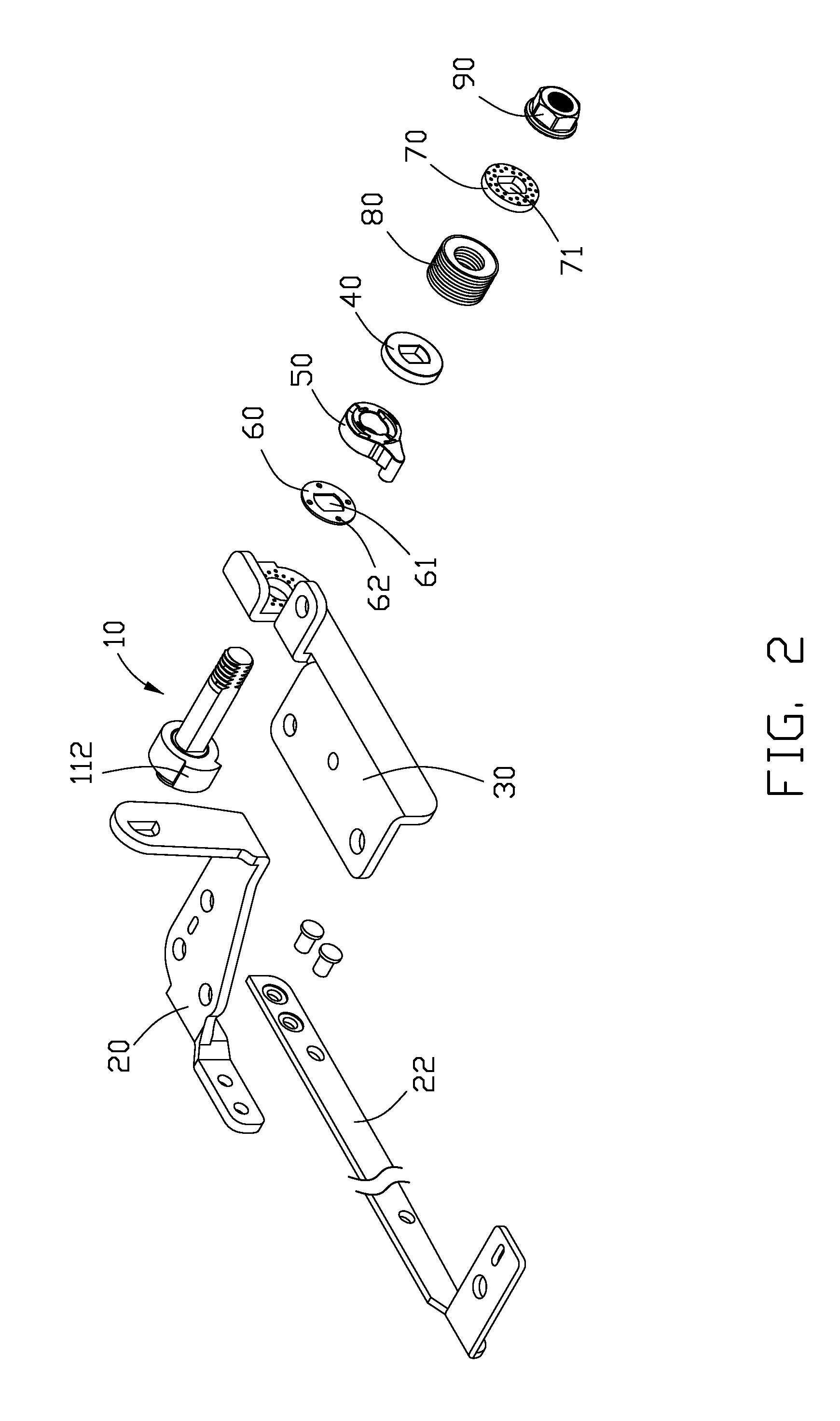
[0011]Referring to FIGS. 1 and 2, an exemplary embodiment of a hinge is adapted to be mounted to a collapsible device, such as a notebook or a clamshell mobile phone, that includes two parts rotatably connected to each other via the hinge. The hinge includes a shaft 10, a rack 20, a bracket 30, a first interfering member 40, a second interfering member 50, two washers 60 and 70, a resilient assembly 80, and a fastener 90.

[0012]The shaft 10 includes a generally cylindrical-shaped head 11, with a post 12 and an engaging portion 13 protruding from opposite sides of the head 11. A stopper 112 protrudes from a circumference of the head 11. The shaft 10 has a noncircular, such as double-D shaped, cross section. The distal end away from the head 11 of the shaft 10 forms a threaded portion. A cross section of the engaging portion 13 is semicircular to fix the shaft 10 to the rack 20. In other embodiments, the cross section of the engaging portion 13 may be any other shape that also enables ...


PUM


Abstract

A hinge includes a rack, a shaft, and a bracket. The shaft includes a head with a stopper protruded thereon. A first side of the head is secured on the rack, and a second side of the head forms a post thereon. The bracket defines a pivoting hole. The bracket forms a restricting block adjacent the pivoting hole. The post is capable of rotating in the pivoting hole and the restricting block is capable of resisting against the stopper of the shaft to prevent the post from further rotating.

Description

CROSS-REFERENCE TO RELATED APPLICATION[0001]Relevant subject matter is disclosed in a co-pending U.S. patent application (application Ser. No. 12 / 205,932; Attorney Docket No. US20954) filed on Sep. 8, 2008 and entitled “HINGE AND INTERFERENCE ASSEMBLY THEREOF”, which is assigned to the same assignee as this patent application. The disclosure of the co-pending application is incorporated herein by reference.BACKGROUND[0002]1. Technical Field[0003]The disclosure relates to mechanical structures and, particularly, to a hinge.[0004]2. Description of Related Art[0005]A collapsible device, such as a notebook computer or clamshell mobile phone, generally includes two parts pivotally connected via a hinge. The hinge generally includes a bracket mounted to one part and a shaft with one end mounted to the other part. The bracket includes a barrel rotatably receiving an opposite end of the shaft.[0006]For protecting the collapsible device from damage caused by excessive rotation of the hinge, ...

Claims


Application Information

Patent Timeline
IPC IPC(8): E05D11/10
CPCG06F1/1616G06F1/1681H04M1/0216
Inventor WANG, SHIN-YUAN
Owner HON HAI PRECISION IND CO LTD
Learn More