Breather apparatus for engine

a breather and engine technology, applied in the direction of crankcase ventillation, combustion engines, machines/engines, etc., can solve the problems of soiling of air cleaners, difficulty in completely removing oil mist from blowby gas, etc., and achieve the effect of avoiding complicated construction of breather apparatus

Inactive Publication Date: 2012-04-05
SUBARU CORP
View PDF3 Cites 11 Cited by
  • Summary
  • Abstract
  • Description
  • Claims
  • Application Information

AI Technical Summary

Benefits of technology

[0006]The object of the present invention is to remove a large amount of oil mist from blowby gas while avoiding complicated construction of the breather apparatus.

Problems solved by technology

This blowby gas becomes a cause of air pollution, so it is necessary that the blowby gas be returned again to the combustion chamber and burned.
By using the breather apparatus disclosed in Japanese Laid-open Patent Publication No. 2009-30580, it was possible to remove a large amount of oil mist from the blowby gas, however, it was difficult to completely remove the oil mist from the blowby gas.
The oil mist that is included in the blowby gas is a cause of soiling of the air cleaner element of the air intake system.

Method used


Image

  • Breather apparatus for engine
  • Breather apparatus for engine
  • Breather apparatus for engine

Examples


Embodiment Construction

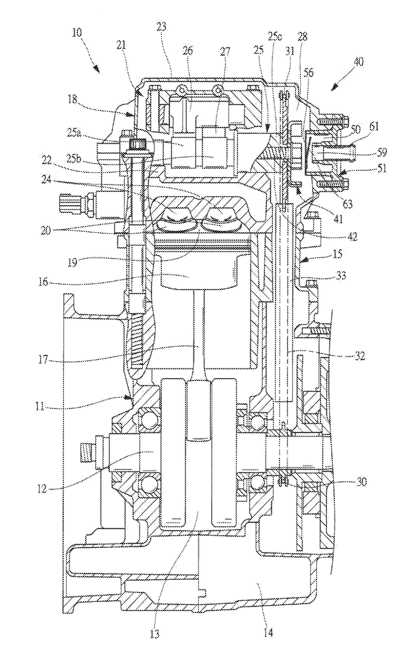
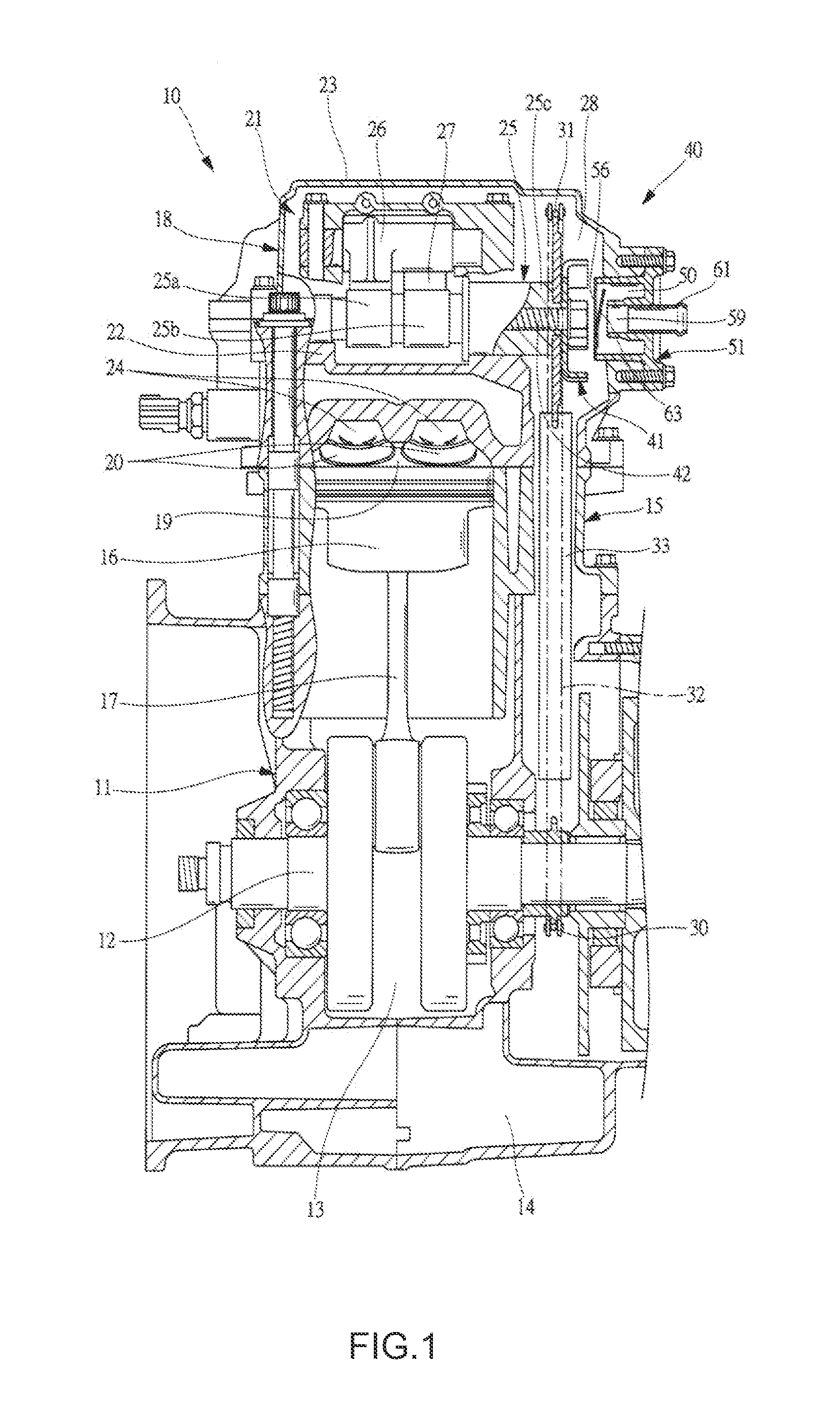
[0039]In the following, an embodiment of the present invention will be explained in detail based on the drawings. FIG. 1 is a cross-sectional view of the internal construction of an engine 10. As illustrated in FIG. 1, the engine 10 has a crankcase 11, and in this crankcase 11 there is a crank chamber 13 that houses the crankshaft 12, and an oil chamber 14 that stores oil (lubrication oil). A cylinder 15 is assembled on the top end of the crankcase 11, and a piston 16 is housed inside the cylinder 15 such that it can freely move back and forth. The crankshaft 12 and the piston 16 are connected via a connecting rod 17. Furthermore, a cylinder head 18 is mounted on the top end of the cylinder 15, and an air intake 20 that opens to a combustion chamber 19 and an exhaust outlet (not illustrated in the figures) are formed in this cylinder head 18. A carburetor and air cleaner box (not illustrated in the figure) of the air intake system 58, which is described below, are connected to the a...


PUM


Abstract

This breather apparatus has a rotation separator that is fastened to a camshaft, and that rotation separator has a base plate section and a plurality of protruding plates that extend from the base plate section. Moreover, a separator housing is provided in the cylinder head, and comprises an air intake on one end, and an exhaust outlet on the other end. Furthermore, a reed valve that opens and closes by the change in pressure inside a cam chamber is provided in the air intake. Blowby gas that is guided to the cam chamber hits against the protruding plates when passing in the radial direction of the rotation separator, and oil mist is captured by those protruding plates. Continuing, the blowby gas is guided from the cam chamber into the separator housing via the reed valve. When passing through the reed valve, the flow rate of the blowby gas changes, so oil mist is effectively captured by the inner wall surface of the separator housing.

Description

CROSS REFERENCE TO RELATED APPLICATION[0001]This application claims priority under 35 U.S.C. 119 based upon Japanese Patent Application Serial No. 2010-221041, filed on Sep. 30, 2010. The entire disclosure of the aforesaid application is incorporated herein by reference.FIELD OF THE INVENTION[0002]The present invention relates to an engine breather apparatus that separates oil mist from blowby gas that is led from the crankcase toward the air intake system.BACKGROUND OF THE INVENTION[0003]Blowby gas flows from the combustion chamber of an engine, through the gap between the piston and cylinder and into the crankcase. This blowby gas becomes a cause of air pollution, so it is necessary that the blowby gas be returned again to the combustion chamber and burned. Therefore, a breather apparatus is used, and by connecting the cylinder head with the air intake system by a breather pipe, this breather apparatus leads the blowby gas from the crankcase to the air intake system.[0004]However,...

Claims


Application Information

Patent Timeline
Patent Type & Authority Applications(United States)
IPC IPC(8): F01M13/04
CPCF01M13/022F01M2013/0422F01M13/0416F01M13/04
Inventor MATSUSHIMA, TOSHIYUKI
Owner SUBARU CORP
Why Eureka
Try Eureka