Waterproof connector and method of producing rubber stopper

a technology of rubber stopper and connector, which is applied in the direction of manufacturing tools, coupling device connections, other domestic objects, etc., can solve the problem that the rubber stopper cannot be accommodated, and achieve the effect of less complicated construction and less complicated construction

Active Publication Date: 2013-10-29
SUMITOMO WIRING SYST LTD
View PDF19 Cites 11 Cited by
  • Summary
  • Abstract
  • Description
  • Claims
  • Application Information

AI Technical Summary

Benefits of technology

[0009]The cavities may be of several sizes for accommodating terminal fittings of different sizes. The cavities may be located at dot-symmetrical positions when the stopper accommodation recess is viewed from the rear. The positioning part is inwardly concave over a whole thickness range of the rubber stopper at dot-symmetrical positions of a peripheral portion of the rubber stopper. The positioning receiving part preferably is on an inner surface of a peripheral wall of the stopper accommodation part or an inner surface of a peripheral wall of the holder at dot-symmetrical positions corresponding to positions of the positioning part. Therefore even if the rubber stopper rotates 180 degrees on its central position, the rubber stopper can be mounted on the stopper accommodation recess or the holder. Consequently, there is no need to care about whether the rubber stopper is upside down, thereby lightening the workload of the operator.
[0010]Two lips preferably are formed side by side in a thickness direction of the rubber stopper along an entire periphery of the rubber stopper. The positioning part includes a concavity at a valley disposed between the lips in a depth direction thereof. The concavity is formed by a sliding die movable in a plane direction of the rubber stopper. A prior art rubber stopper formed by a pair of dies may attach to the movable die when the dies are opened. However, the above-described sliding die prevents the rubber stopper from attaching to the movable die when the dies are opened. Further the concavity of the positioning part is formed by the sliding die, thereby avoiding complexly constructed dies.
[0011]The concavity preferably is formed at one side of a specified wire insertion hole near the periphery of the rubber stopper. A concave cut-off part is formed in the depth direction of the valley between the lips at the other side of the specified wire insertion hole. Thus, a half-circumference region on a periphery of the specified wire insertion hole and near a side edge of the rubber stopper has an almost equal radial dimension throughout an entire circumference. As a result, the rubber stopper imparts an almost uniform elastic reaction force to the half-circumference region of the electric wire inserted through the specified wire insertion hole and the periphery of the electric wire is sealed with a favorable balance.
[0013]The method also preferably includes forming a positioning part at a specified position on the periphery of the rubber stopper for preventing the rubber stopper from being mounted on an object in an incorrect posture. The step of forming the positioning part preferably includes forming a concavity at a valley between the lips in a depth direction thereof. The concavity is formed by the sliding die. Thus, there is no need to use a dedicated die for forming the concavity and the dies have a less complicated construction.
[0014]The concavity preferably is formed at one side of a specified wire insertion hole near the periphery of the rubber stopper. The method also preferably includes forming a cut-off concave part in the depth direction of the valley between the lips and at other side of the specified wire insertion hole. Thus, a half-circumference region on a periphery of the specified wire insertion hole has almost an equal radial dimension throughout an entire circumference. The cut-off part is formed by the sliding die. Thus, there is no need for a dedicated die to form the cut-off part and the dies have a less complicated construction.

Problems solved by technology

However, the positioning part interferes with the positioning receiving part when the rubber stopper is in an incorrect posture relative to the stopper accommodation part or the holder so that the rubber stopper cannot be accommodated in the stopper accommodation part or on the holder.

Method used


Image

  • Waterproof connector and method of producing rubber stopper
  • Waterproof connector and method of producing rubber stopper
  • Waterproof connector and method of producing rubber stopper

Examples


Embodiment Construction

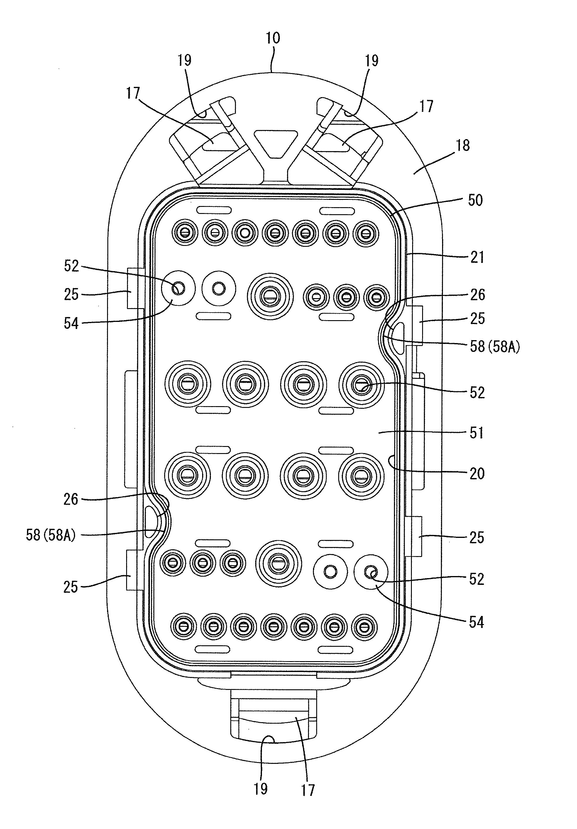
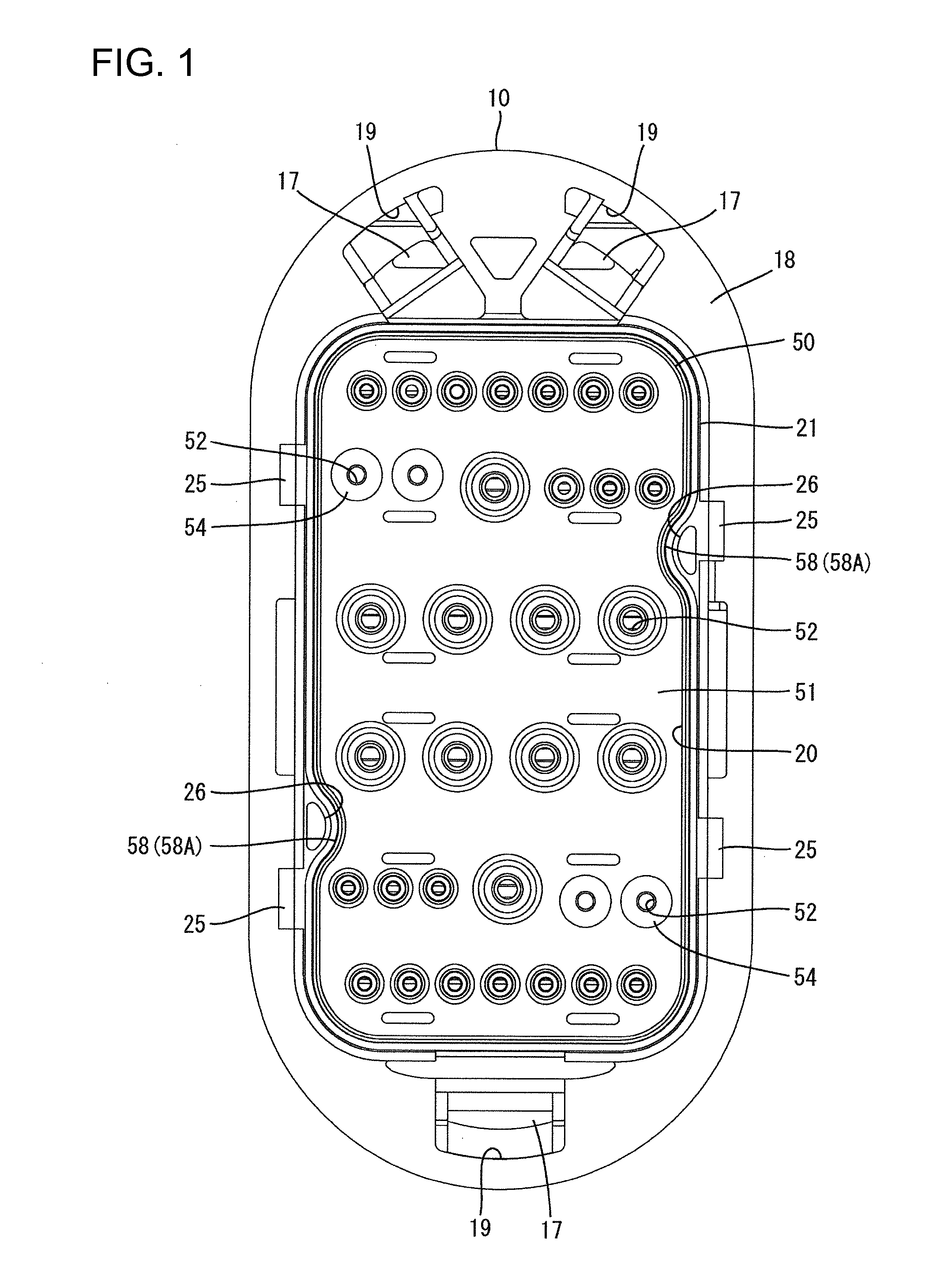
[0024]A waterproof connector in accordance with the invention has a housing 10, a rubber stopper 50, a holder 70, and terminal fittings 80, as shown in FIGS. 1 through 9. The housing 10 can be fit on an unshown mating housing. The end of the housing 10 that can be fit on the mating housing is referred to herein as the front.

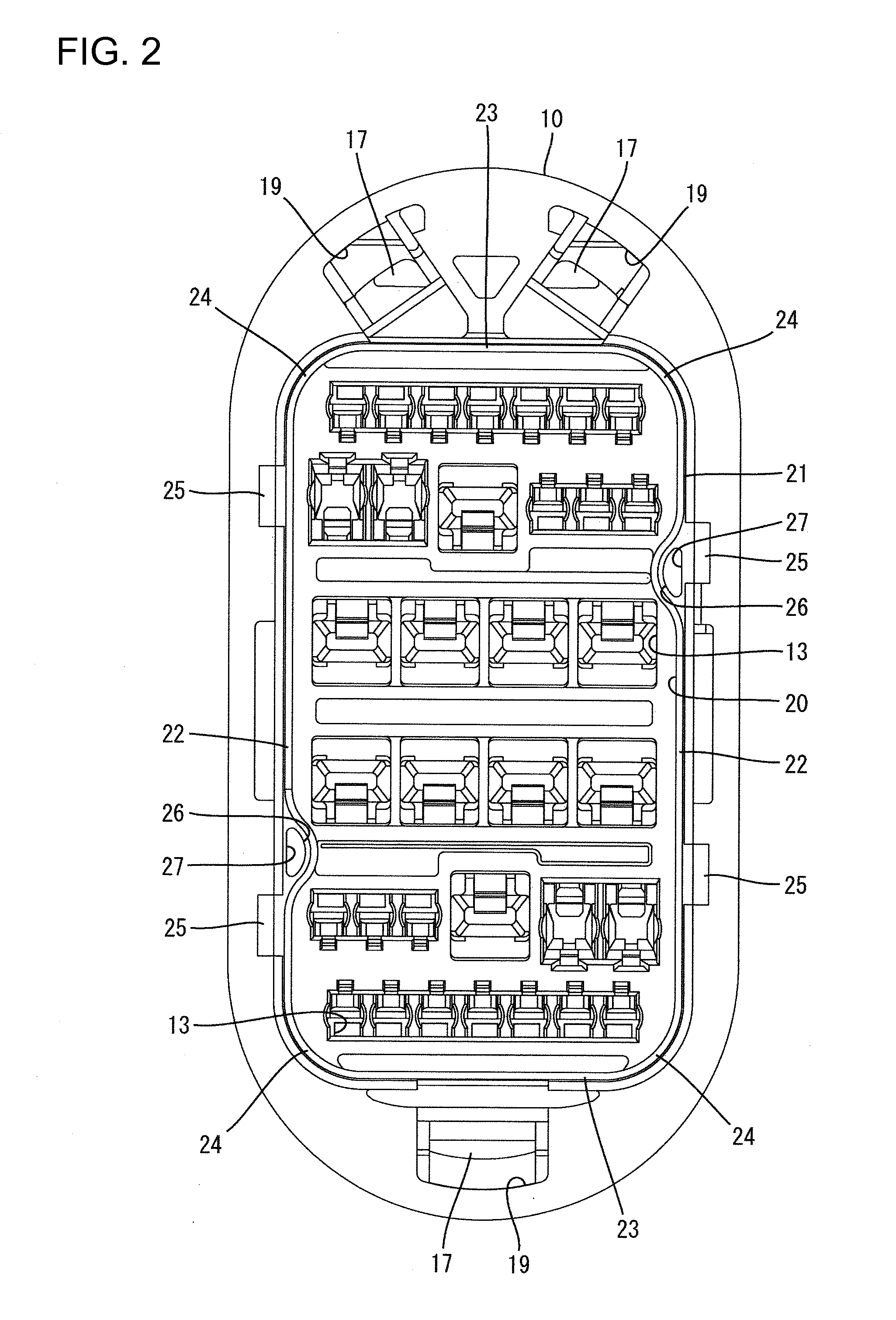
[0025]As shown in FIGS. 4 and 5, the housing 10 has a block-shaped body 11 long in the height direction and a tubular hood 12 projects forward from the periphery of a front end of the body 11. Cavities 13 penetrate through the body 11 in front to rear directions and are arranged in height and width directions. A flexible lance 14 projects forward from an inner wall of each cavity 13. One of the terminal fittings 80 is inserted into each cavity 13 from the rear, and the properly inserted terminal fitting 80 is locked in the cavity 13 by the lance 14.

[0026]The terminal fittings 80 are formed by punching a conductive metal plate and thereafter bending the obtained c...


PUM

PropertyMeasurementUnit
sizesaaaaaaaaaa
thicknessaaaaaaaaaa
radial dimensionaaaaaaaaaa

Abstract

A waterproof connector has a housing (10) with a rearwardly open stopper accommodation part (20). A rubber stopper (50) is accommodated in the stopper accommodation part (20) and has wire insertion holes (52). A holder (70) is mounted on the housing (10) for preventing the rubber stopper (50) from being removed from the stopper accommodation part (20). A positioning part (58) is formed on the rubber stopper (50). A positioning receiving part (26) is formed on the stopper accommodation part (20) and mates with the positioning part (58) when the rubber stopper (50) is in a correct posture so that the rubber stopper (50) can fit in the stopper accommodation part (20). The positioning part (58) interferes with the positioning receiving part (26) when the rubber stopper (50) is in an incorrect posture so that the rubber stopper (50) cannot fit in the stopper accommodation part (20).

Description

BACKGROUND OF THE INVENTION[0001]1. Field of the Invention.[0002]The invention relates to a waterproof connector and a method of producing a rubber stopper to be used for the waterproof connector.[0003]2. Description of the Related Art.[0004]U.S. Pat. No. 7,114,991 discloses a waterproof connector with a housing that has cavities, each of which can accommodate a terminal fitting. An open rubber stopper accommodation part is formed on a rear surface of the housing and a rubber stopper is accommodated in the rubber stopper accommodation part. The rubber stopper has a plurality of electric wire insertion holes that communicate with the respective cavities. A holder is mounted on the housing and prevents the rubber stopper from being removed from the rubber stopper accommodation part.[0005]The rubber stopper has the shape of a rectangular mat with a predetermined thickness and has four rounded corners when viewed from the front and rear.[0006]The conventional rubber stopper may be inver...

Claims


Application Information

Patent Timeline
Patent Type & Authority Patents(United States)
IPC IPC(8): H01R13/40
CPCB29C45/2628B29C45/44H01R13/5208
Inventor HAN, CHAN CHUNG
Owner SUMITOMO WIRING SYST LTD
Why Eureka
Try Eureka