Frame structure for work vehicle

a work vehicle and frame technology, applied in the direction of vehicle components, pivoted suspension arms, resilient suspensions, etc., can solve the problems of higher costs and more complex configurations, and achieve the effect of simplifying the configuration and ensuring the smooth rid

Active Publication Date: 2009-10-13
KUBOTA LTD
View PDF5 Cites 54 Cited by
  • Summary
  • Abstract
  • Description
  • Claims
  • Application Information

AI Technical Summary

Benefits of technology

[0008]An object of the present invention is to provide a work vehicle having an improved frame in which the configuration is simplified and a smooth ride can be ensured.
[0018]According to this aspect, the engine and the transmission devices are installed along with the left and right front wheels on the auxiliary frame suspended via the suspension on the vehicle body frame, whereby the engine and the transmission devices are displaced integrally along with the left and right wheels in relation to the vehicle body frame when the suspension reduces vibrations or shocks from the road. Therefore, there is no need to provide the power transmission system for the left and right wheels with universal couplings or the like so as to allow the left and right wheels to be displaced in relation to the engine and the transmission devices.
[0019]Therefore, it is possible to simplify the configuration by reducing the number of components and to ensure a smooth ride in which vibrations or shocks from the road are reduced and engine vibrations are absorbed.

Problems solved by technology

In other words, attempting to create a smoother ride by reducing vibrations or shocks from the road with a suspension and by absorbing engine vibrations with anti-vibration rubber pads has led to more complex configurations and higher costs due to installing a plurality of universal couplings or the like.

Method used


Image

  • Frame structure for work vehicle
  • Frame structure for work vehicle
  • Frame structure for work vehicle

Examples


Embodiment Construction

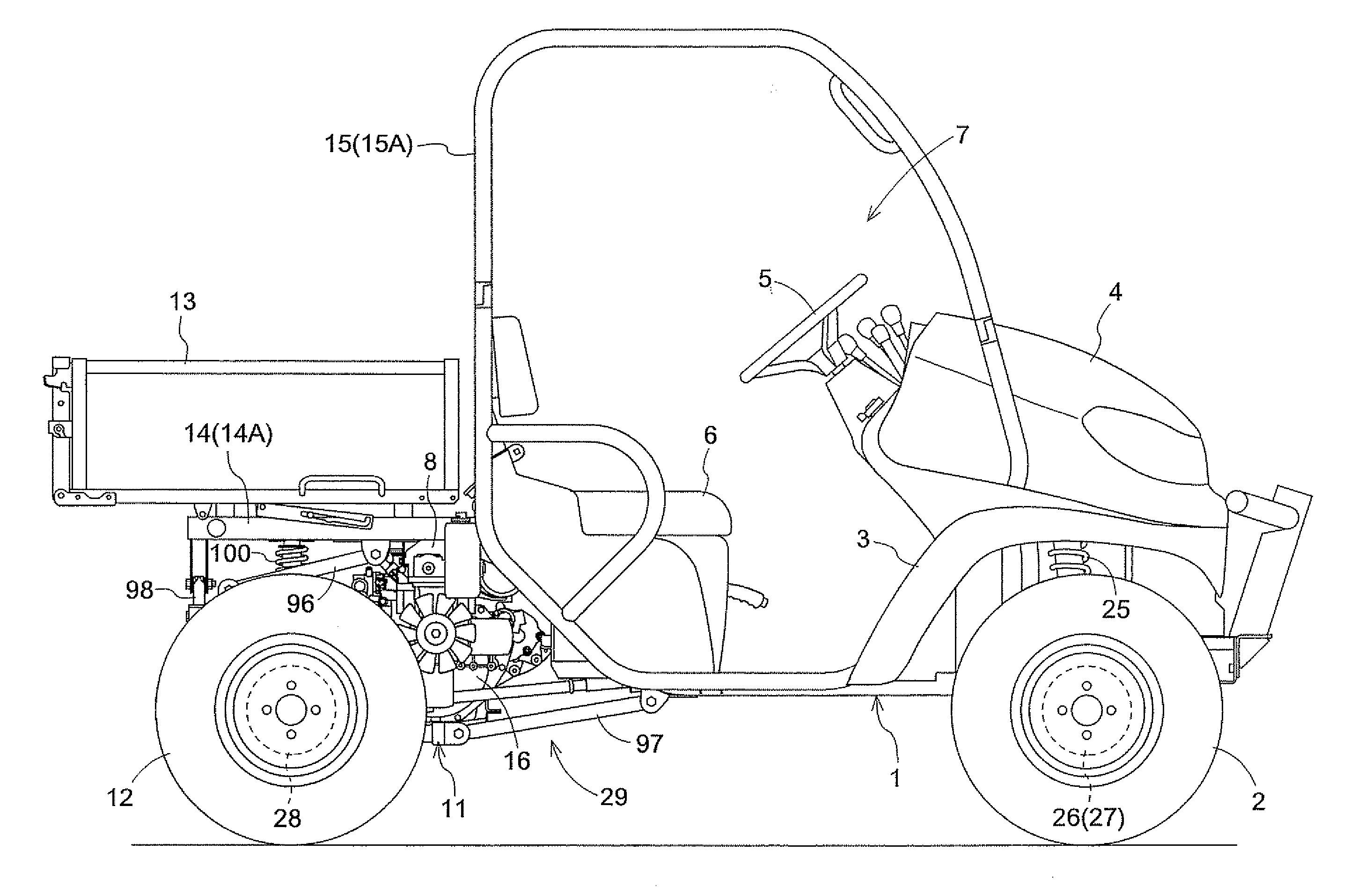
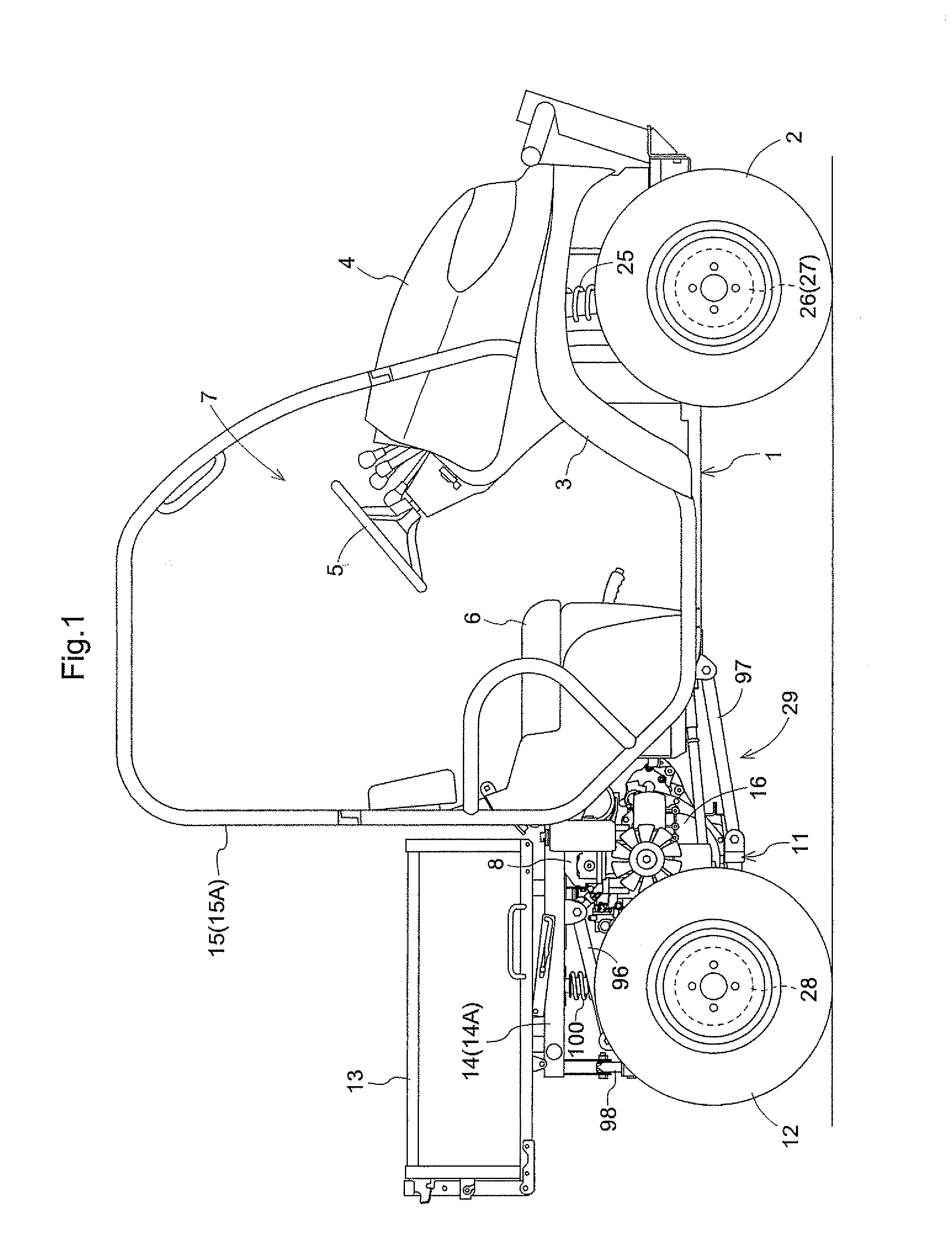
[0039]An embodiment in which the power transmission structure for a work vehicle according to the present invention is applied to a multipurpose work vehicle, which is an example of a work vehicle, will be described hereinbelow as an example of a preferred embodiment for carrying out the present invention, with reference to the drawings.

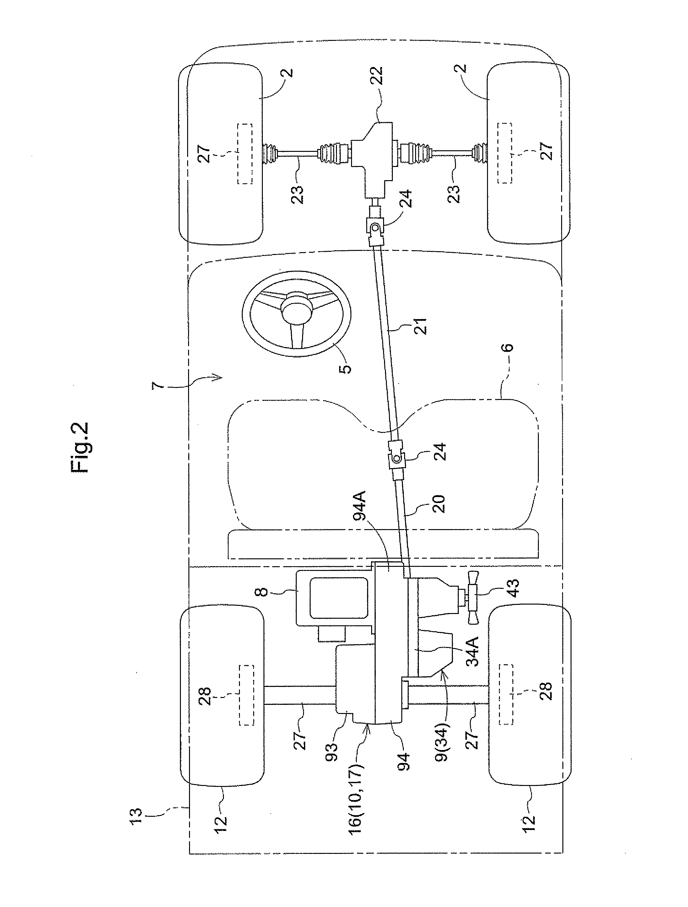
[0040]FIG. 1 is an overall side view of a multipurpose work vehicle. FIG. 2 is a schematic plan view showing the power transmission configuration of the multipurpose work vehicle. The multipurpose work vehicle comprises a pair of left and right front wheels 2, a bottom cover 3 that doubles as a front fender, a hood 4, and other components installed on the front of a vehicle body frame 1, as shown in these drawings. In the longitudinal middle of the vehicle body frame 1, a steering wheel 5 for steering the front wheels, a sofa-style seat 6, and other components are provided to form a cab 7. At the rear of the vehicle body frame 1 are installed an engi...


PUM


Abstract

A work vehicle comprising a pair of left and right wheels; a vehicle body frame supported at least partially by the pair of left and right wheels; and a suspension provided between the pair of left and right wheels and the vehicle body frame, the suspension being a five-linkage type rigid axle suspension including: a pair of left and right upper arms and a pair of left and right lower arms for positioning the pair of left and right wheels in the longitudinal direction of the vehicle body, a lateral rod for positioning the pair of left and right wheels in the lateral direction of the vehicle body, a pair of left and right coil springs for absorbing shocks from the road, and a pair of left and right dampers for controlling the movements of the pair of left and right coil springs. An auxiliary frame is further provided for supporting the pair of left and right wheels, an engine, and a transmission device, wherein the auxiliary frame is suspended on the vehicle body frame via the suspension.

Description

BACKGROUND OF THE INVENTION[0001]1. Field of the Invention[0002]The present invention relates to frame structure for a work vehicle in which a vehicle body frame is provided with suspension for suspending a pair of left and right vehicle wheels.[0003]2. Description of the Related Art[0004]In one example of a vehicle body structure for a work vehicle such as is described above, the engine is mounted via a plurality of anti-vibration rubber pads to an engine mounting frame connected to a main frame, a transmission case and a hydraulic continuously variable transmission are installed in a transmission support frame connected to the main frame, and a pair of left and right rear wheels driven by power from the engine is suspended on the main frame via a leaf spring type of rigid axle suspension (for example, see Japanese Laid-open Patent Application No. 2004-50954).[0005]In the configuration described above, since the left and right rear wheels driven by power from the engine are suspend...

Claims


Application Information

Patent Timeline
Patent Type & Authority Patents(United States)
IPC IPC(8): B62D21/11
CPCB60G9/022B60G2300/13B60G2200/326
Inventor BESSHO, HIROKIHORIUCHI, YOSHIFUMI
Owner KUBOTA LTD
Why Eureka
Try Eureka