Anti-relief fan frame body structure

a fan frame and anti-relief technology, applied in the direction of machines/engines, stators, liquid fuel engines, etc., can solve the problems of affecting the reliability of products, the fan is likely to operate unstably, and the product is likely to be damaged, so as to increase the performance of the fan, increase the air volume of the fan, and increase the effect of the fan

Active Publication Date: 2015-01-20
ASIA VITAL COMPONENTS SHENZHEN CO LTD
View PDF11 Cites 2 Cited by
  • Summary
  • Abstract
  • Description
  • Claims
  • Application Information

AI Technical Summary

Benefits of technology

[0013]A primary object of the present invention is to provide an anti-relief fan frame body structure, which can increase the performance of the fan.
[0014]A further object of the present invention is to provide the above anti-relief fan frame body structure, which can effectively increase air volume of the fan without changing any dynamic blade or static blade of the fan.
[0015]To achieve the above and other objects, the anti-relief fan frame body structure of the present invention includes a frame body and multiple anti-relief sections. The frame body has a receiving space and a shaft seat received in the receiving space. The frame body further has multiple flow guide members extending from a circumference of shaft seat to an inner circumference of the frame body to connect with the inner circumference of the frame body. The anti-relief sections are disposed on the inner circumference of the frame body between the flow guide members to increase the performance of the fan.

Problems solved by technology

As a result, the electronic products are likely to operate unstably.
This will affect reliability of the products and shorten lifetime of the products.
Therefore, it has become a critical issue how to dissipate the heat generated by the electronic products.
The eddy will cause deterioration of the performance (such as air volume) of the fan.
However, the annular body 14 leads to another problem.
As a result, the fluid can hardly flow smoothly.
This will lead to deterioration of the performance of the fan and make great noise.
1. The performance of the fan is deteriorated.
2. The fan will make great noise in operation.

Method used


Image

  • Anti-relief fan frame body structure
  • Anti-relief fan frame body structure
  • Anti-relief fan frame body structure

Examples


Embodiment Construction

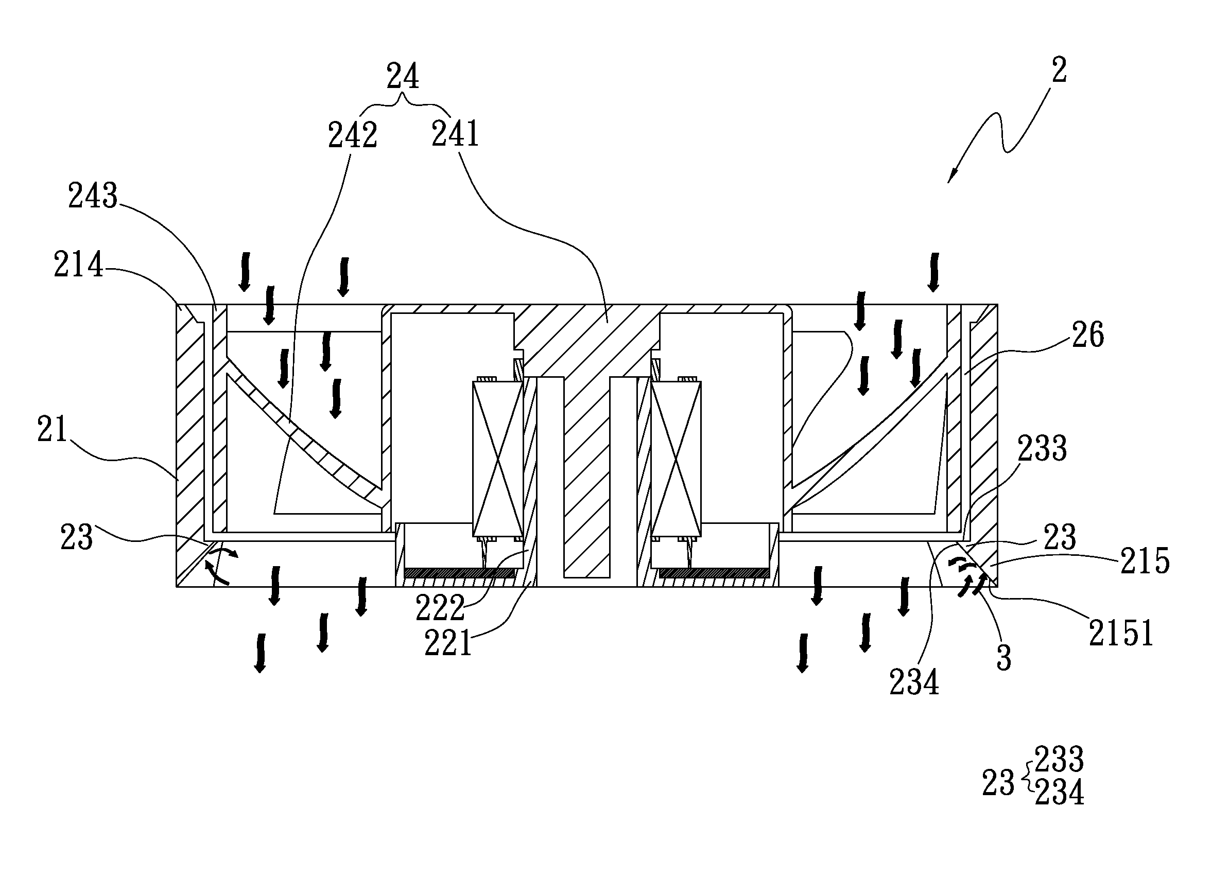
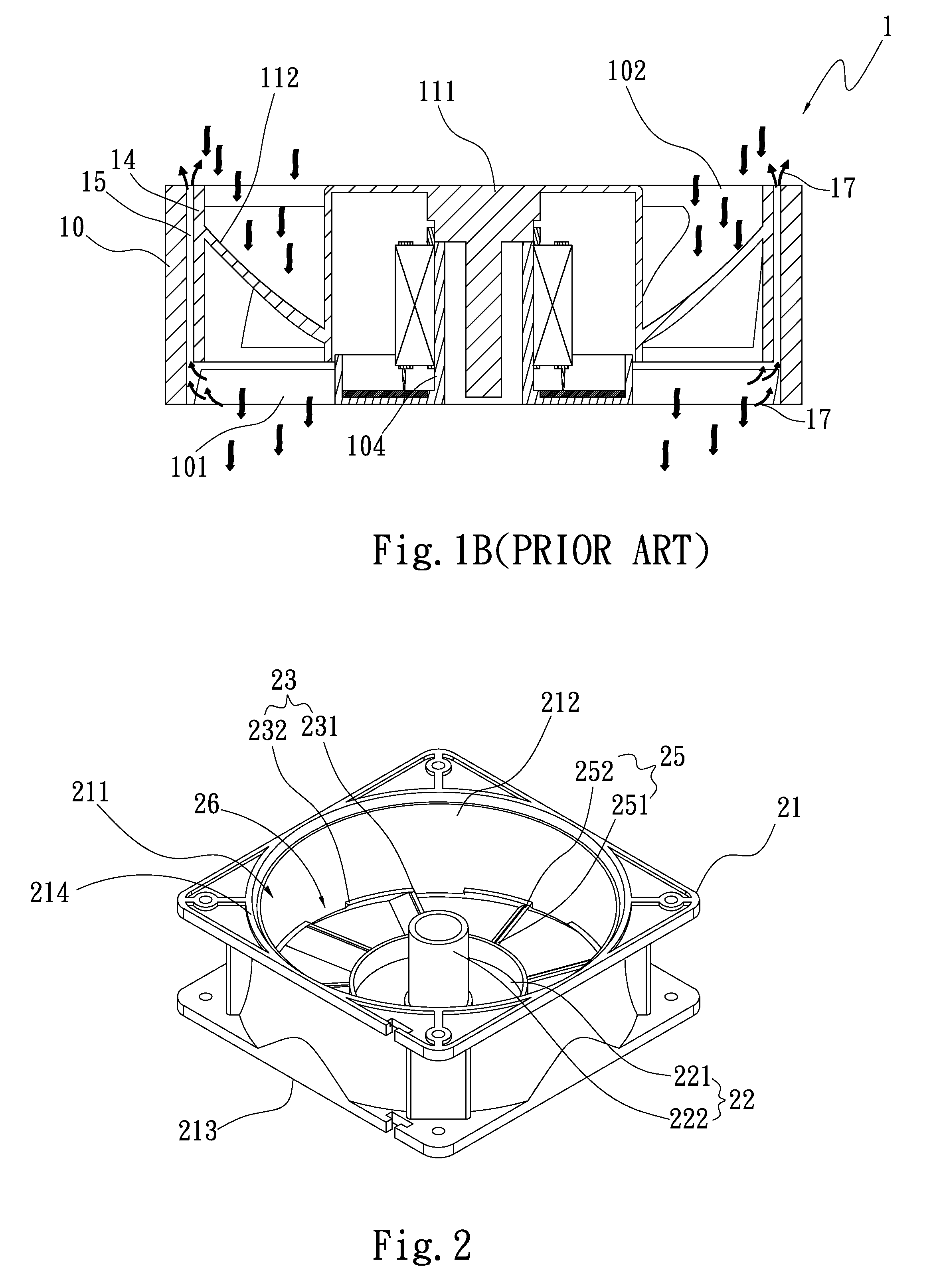
[0027]Please refer to FIGS. 2, 3 and 4. FIG. 2 is a perspective view of a first embodiment of the present invention. FIG. 3 is a perspective assembled view of the fan of the present invention. FIG. 4 is a sectional assembled view of the first embodiment of the fan of the present invention. According to the first embodiment, the anti-relief fan frame body structure of the present invention includes a frame body 21 and multiple anti-relief sections 23. The frame body 21 has a receiving space 211, a top portion 214, a bottom portion 215 and a shaft seat 22. The receiving space 211 has a wind inlet side 212 and a wind outlet side 213 opposite to the wind inlet side 212. The top portion 214 and the bottom portion 215 are disposed in adjacency to the wind inlet side 212 and the wind outlet side 213, respectively. The bottom portion 215 comprises a stop backflow inclined surface 2151 which is upward obliquely extending from an edge of the bottom portion 215 of the frame body 21 toward the ...


PUM


Abstract

An anti-relief fan frame body structure includes a frame body and multiple anti-relief sections. The frame body has a receiving space and a shaft seat received in the receiving space. The frame body further has multiple flow guide members extending from a circumference of shaft seat to an inner circumference of the frame body to connect with the inner circumference of the frame body. The anti-relief sections are disposed on the inner circumference of the frame body between the flow guide members to increase the performance of the fan.

Description

BACKGROUND OF THE INVENTION[0001]1. Field of the Invention[0002]The present invention relates generally to a fan frame body structure, and more particularly to an anti-relief fan frame body structure, which can increase the performance of the fan.[0003]2. Description of the Related Art[0004]Following the rapid development of high-performance, high-frequency, high-speed and slimmed electronic products, the electronic products generate more and more heat in operation. As a result, the electronic products are likely to operate unstably. This will affect reliability of the products and shorten lifetime of the products. Therefore, it has become a critical issue how to dissipate the heat generated by the electronic products. In general, a cooling fan is often used as a heat dissipation for dissipating the heat generated by the electronic products[0005]When a conventional cooling fan operates, eddy is often formed between the blades of the fan. The eddy will cause deterioration of the perf...

Claims


Application Information

Patent Timeline
Patent Type & Authority Patents(United States)
IPC IPC(8): F04D29/54F04D29/32F04D29/16F04D25/06
CPCF04D29/542F04D25/0613F04D29/326F04D29/164
Inventor LIU, WEN-HAOYIN, GUAN-CHEN
Owner ASIA VITAL COMPONENTS SHENZHEN CO LTD
Why Eureka
Try Eureka