Fan frame structure

A fan and frame technology, which is applied in the field of fan frame, can solve the problems of shortened or damaged shell life, high internal stress, and insufficient bending strength of the side wall, so as to improve fan efficiency, reduce internal stress, and improve bending resistance Insufficient strength effect

Active Publication Date: 2017-11-03
DELTA ELECTRONICS INC
View PDF4 Cites 1 Cited by
  • Summary
  • Abstract
  • Description
  • Claims
  • Application Information

AI Technical Summary

Problems solved by technology

Because the side wall of the traditional housing is made of a single material, when the material of the side wall of the housing is plastic, the bending strength of the side wall will be obviously insufficient.
When the side wall of the housing base is made of metal, it can only be drawn to shape the side wall of the housing base. At this time, the side wall of the housing base will have high internal stress during the manufacturing process, which will lead to the above The side wall part is prone to deformation
Moreover, after forming, the connecting part between the side wall of the housing base and the bottom of the housing base will obviously become thinner and cannot be uniform in thickness. At this time, the housing base is likely to have shortened service life or damage. Technical issues to be improved

Method used


Image

  • Fan frame structure
  • Fan frame structure
  • Fan frame structure

Examples


Embodiment Construction

[0038] The detailed description and technical content of the present invention are described as follows in conjunction with the accompanying drawings. However, the accompanying drawings are only for reference and description, and are not used to limit the present invention.

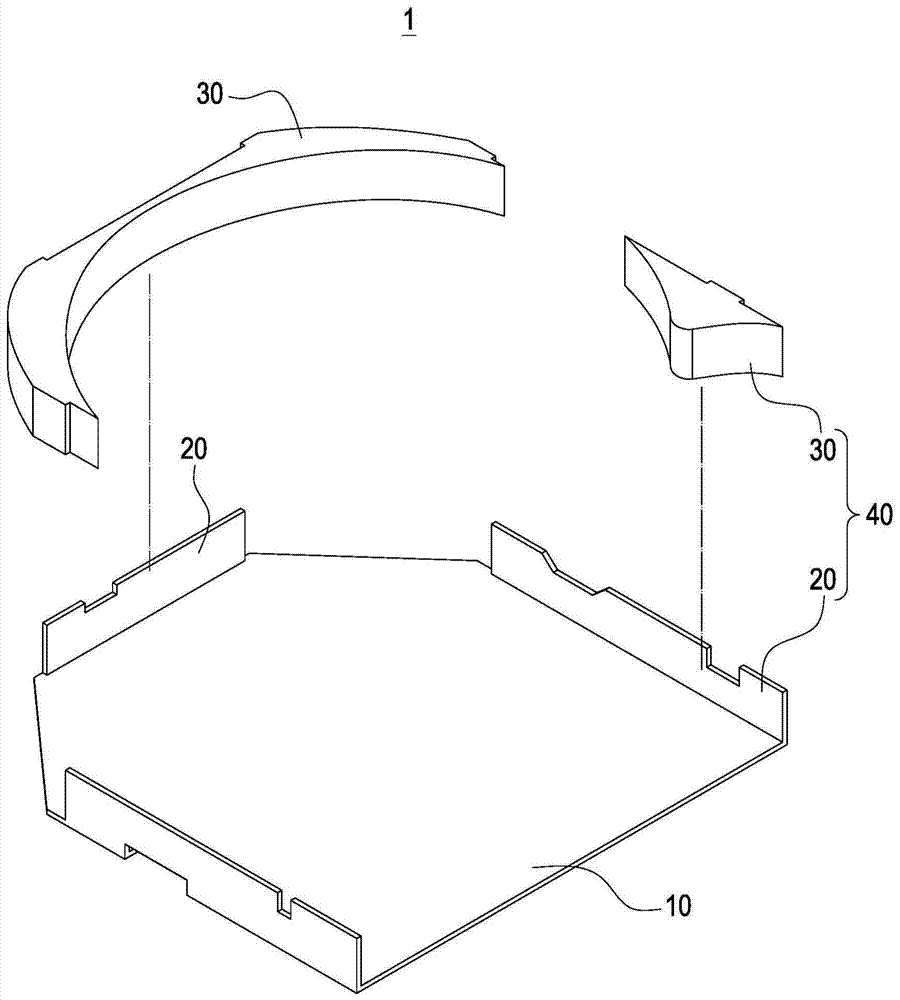
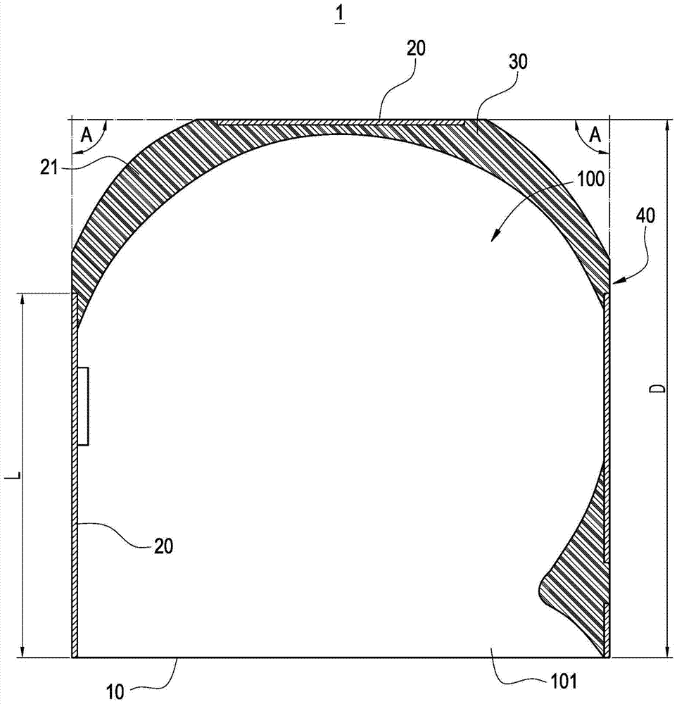
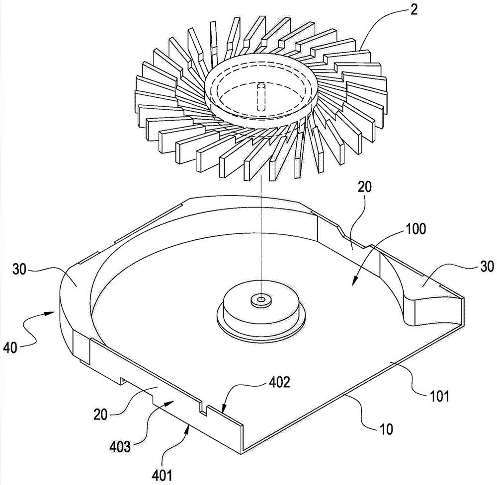
[0039] Please refer to Figure 1 to Figure 3 , Are respectively a three-dimensional exploded schematic view, a combined cross-sectional view, and a schematic view of a combined fan of the fan frame seat structure of the present invention. The present invention provides a fan frame base structure 1 for arranging a fan blade 2. The fan frame structure 1 includes a metal bottom plate 10 and at least one non-metal side wall 30. The metal bottom plate 10 includes at least two metal side plates 20, each of the metal side plates 20 is formed by bending the sides of the metal bottom plate 10, and the at least two metal side plates 20 are flat.

[0040] Furthermore, the at least one non-metal side wall 30 is adjacent ...


PUM


Abstract

The invention discloses a fan frame base structure for placing blades, which comprises a metal baseplate and at least one nonmetal side plate. The metal baseplate comprises at least two metal side plates; each metal side plate is formed by side edges of a bent metal baseplate; and the metal side plates are flat plates. The nonmetal side walls are near the metal side plates; and all the nonmetal side walls and all the metal side plates are mutually staggered to form a fan frame base side wall, wherein the top edges of all the metal side plates and the top edges of all the nonmetal side walls define the top edge of the fan frame base side wall, so that the fan frame base is thinned, the fan efficiency is promoted, and the whole strength of the fan frame base side wall is improved.

Description

Technical field [0001] The invention relates to a fan frame seat, in particular to a side frame structure of the fan frame seat. Background technique [0002] Since electronic devices generate high temperatures during operation, this high temperature can cause damage to electronic components. Therefore, the electronic device is usually equipped with a heat dissipation device, such as a heat dissipation fan, etc., which can take away the hot air inside the electronic device through the airflow generated by the heat dissipation fan, thereby maintaining the normal operation of the electronic device. [0003] Generally, the cooling fan is placed in the housing. However, as electronic devices are becoming thinner and lighter, the cooling fan is becoming thinner. Therefore, the housing base that holds the cooling fan must also gradually reduce the overall height. Because the material of the side wall of the traditional housing is made of a single material, when the material of the side...

Claims


Application Information

Patent Timeline
Patent Type & Authority Patents(China)
IPC IPC(8): F04D29/42
Inventor 吕昭文王君智邱鼎为
Owner DELTA ELECTRONICS INC
Why Eureka
Try Eureka