Cooling fan

a cooling fan and fan body technology, applied in the field of cooling fans, can solve the problems of high noise level, achieve the effects of avoiding operation noise, minimizing friction and hard strength, and reducing installation clearan

Inactive Publication Date: 2011-09-13
TEK CHAIN TECH
View PDF4 Cites 1 Cited by
  • Summary
  • Abstract
  • Description
  • Claims
  • Application Information

AI Technical Summary

Benefits of technology

[0006]The present invention has been accomplished under the circumstances in view. It is one object of the present invention to provide a cooling fan, which eliminates installation clearance to minimize friction and hard strength, avoiding operation noise and improving fan performance.

Problems solved by technology

According to this design, the bearing 14 is press-fitted into the stator 11, friction and hard strength are produced during rotation of the fan blade 15, resulting in a high noise level.

Method used


Image

  • Cooling fan
  • Cooling fan
  • Cooling fan

Examples


Embodiment Construction

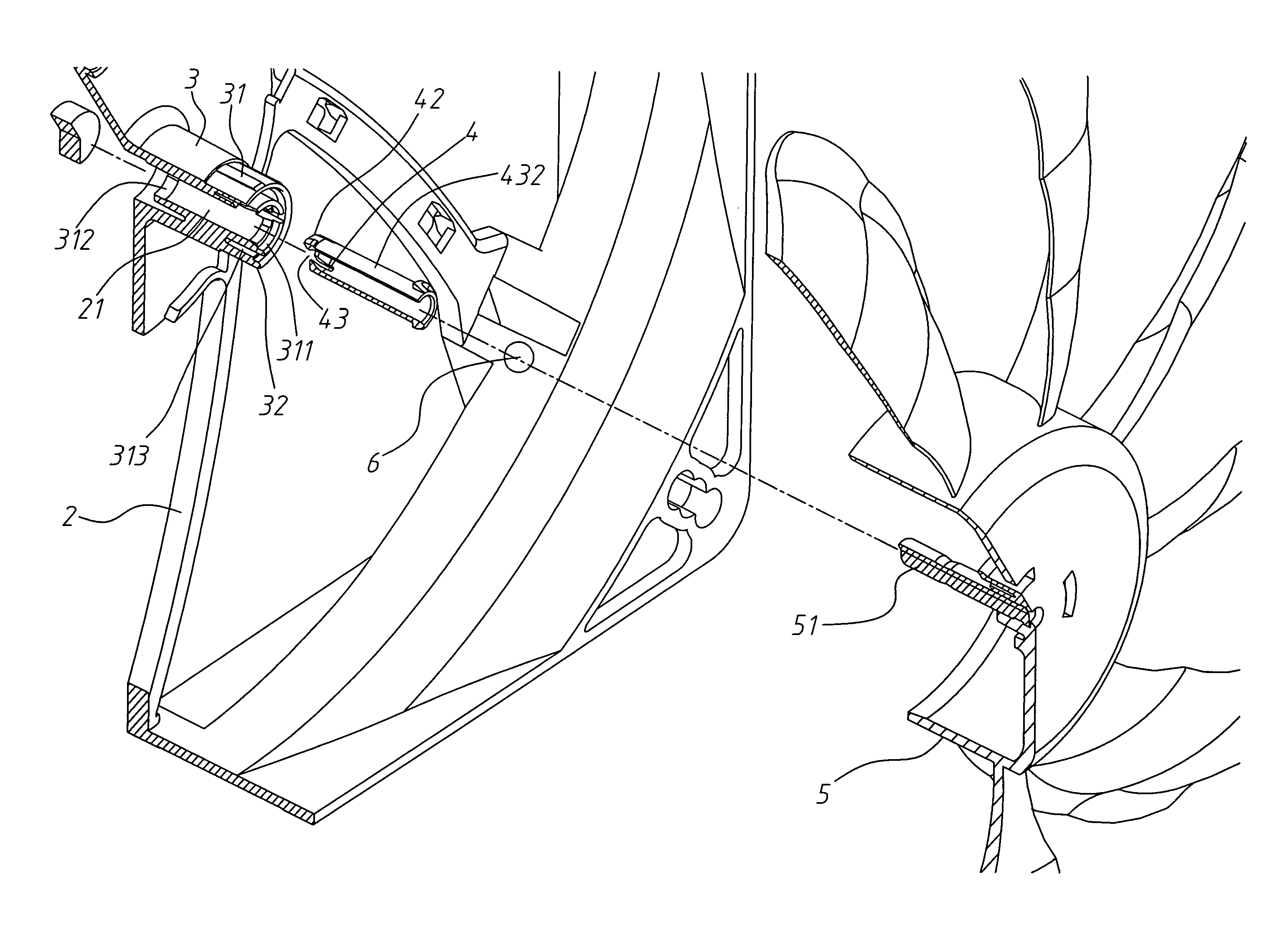
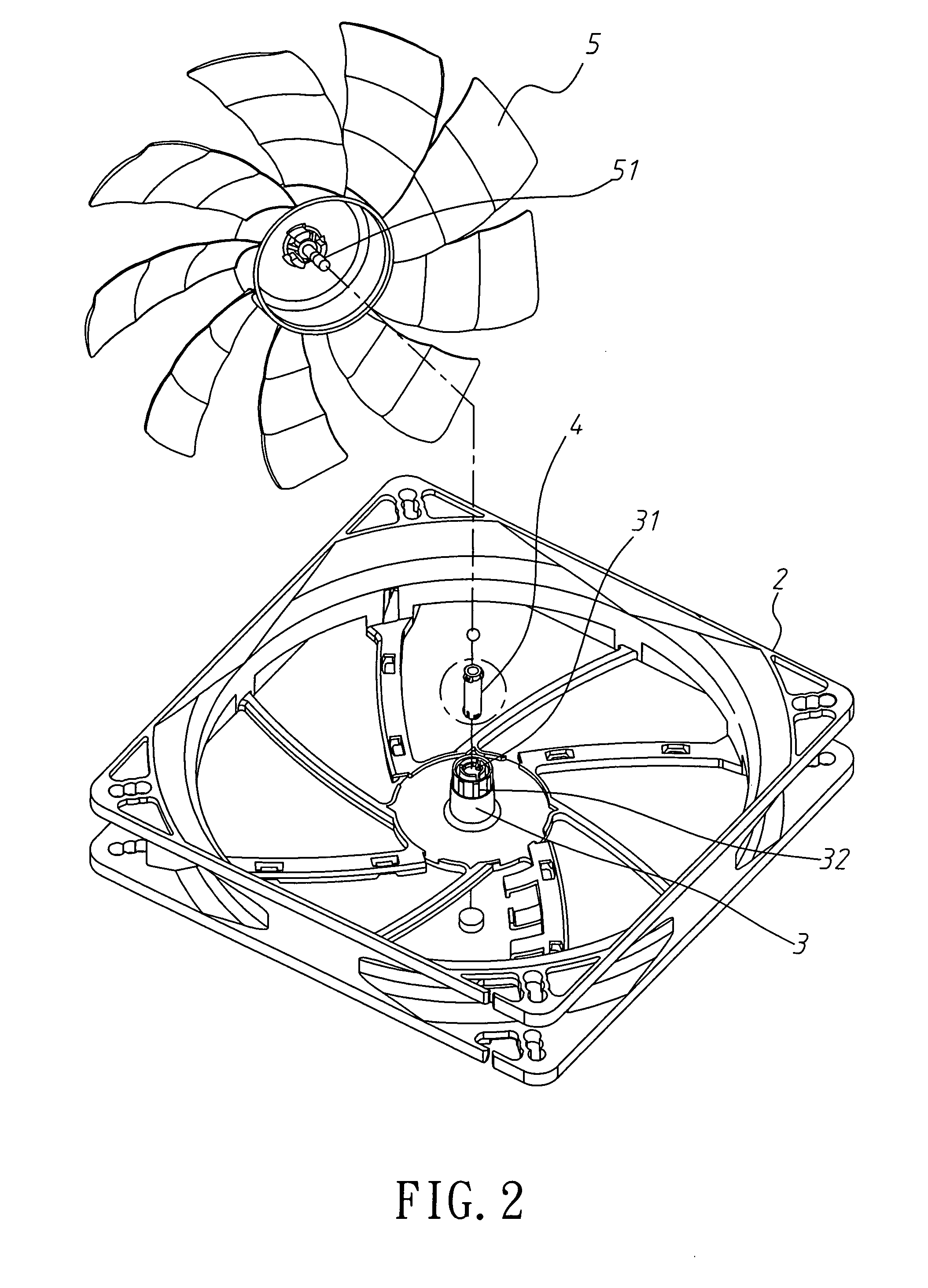
[0016]Referring to FIGS. 2˜4, a cooling fan in accordance with the present invention is shown comprised of a bracket 2, a stator 3, an axle bearing 4, and a fan blade 5. The stator 3 is fixedly mounted in the bracket 2, comprised of an inner sleeve 31 and an outer sleeve 32. The inner sleeve 31 is concentrically disposed inside the outer sleeve 32 with a middle part of the outside wall thereof fixedly connected to a middle part of the inside wall of the outer sleeve 32. The inner sleeve 31 has a first annular inside flange 311 and a second annular inside flange 312 respectively extending around top and bottom ends of the inside wall thereof, and a plurality of longitudinal crevices 313 cut through the top end and the first annular inside flange 311 and equiangularly spaced around the periphery.

[0017]The axle bearing 4 is a tubular bearing having a plurality of first hook blocks 41 protruded from the periphery and equiangularly spaced around one end, namely, the top end, a plurality ...


PUM


Abstract

A cooling fan includes a stator formed of an outer sleeve and an inner sleeve that suspends in the outer sleeve and has a middle part fixedly connected to a middle part of the outer sleeve and a plurality of crevices equiangularly spaced around the top end thereof, a hollow axle bearing inserted into the inner sleeve of the stator and having top and bottom hook blocks respectively hooked on the top and bottom ends of the outer sleeve of the stator and a plurality of crevices equiangularly spaced around the bottom end, a steel ball rotatably supported inside the axle bearing, and a fan blade that has a center axle inserted into the axle bearing and stopped against the steel ball.

Description

BACKGROUND OF THE INVENTION[0001]1. Field of the Invention[0002]The present invention relates to cooling fan and more particularly, to an improved structure of cooling fan that eliminates installation clearance to minimize friction and hard strength, avoiding operation noise and improving fan performance.[0003]2. Description of the Related Art[0004]A typical cooling fan for computer or the like, as shown in FIG. 1, generally comprises a bracket 1, a stator 11 affixed to the bracket 1, a winding 12 wound on the stator 11, a magnetic device 13 arranged around the winding 12, a bearing 14 mounted in the stator 11, an axle 151 coupled to the bearing 14, and a fan blade 15 affixed to the axle 151 for synchronous rotation. When electricity is provided to the winding 12, the winding 12 is energized to induce a magnetic field that acts upon the magnetic device 13, causing rotation of the fan blade 15 with the axle 151. According to this design, the bearing 14 is press-fitted into the stator...

Claims


Application Information

Patent Timeline
Patent Type & Authority Patents(United States)
IPC IPC(8): F04D29/056
CPCF04D29/0467F04D29/057F04D25/062F04D25/0646H01L23/467H01L2924/0002H01L2924/00
Inventor WANG, CHENG-CHIEN
Owner TEK CHAIN TECH
Why Eureka
Try Eureka