

Manufacturing technique and device for composite board
A technology of production process and production equipment, which is applied in the field of composite board production process and its production equipment, can solve problems such as poor bonding performance of the composite interface, achieve the effect of reducing the use of welding rods, reducing workload, and improving processing accuracy
- Summary
- Abstract
- Description
- Claims
- Application Information
AI Technical Summary
Problems solved by technology
Method used
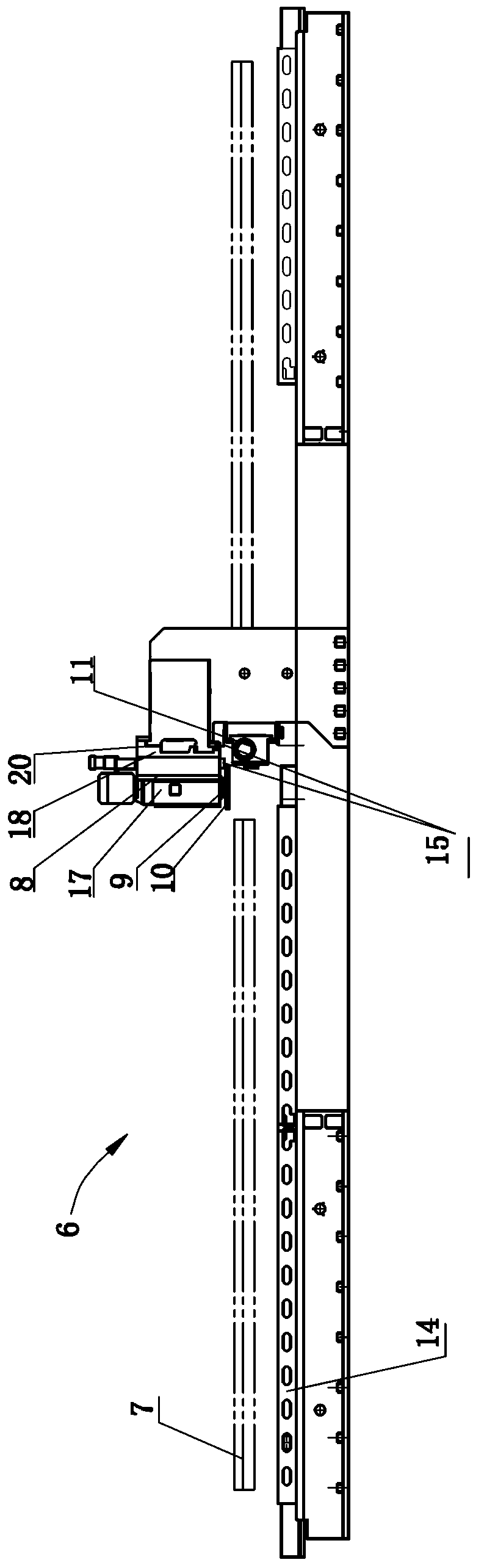
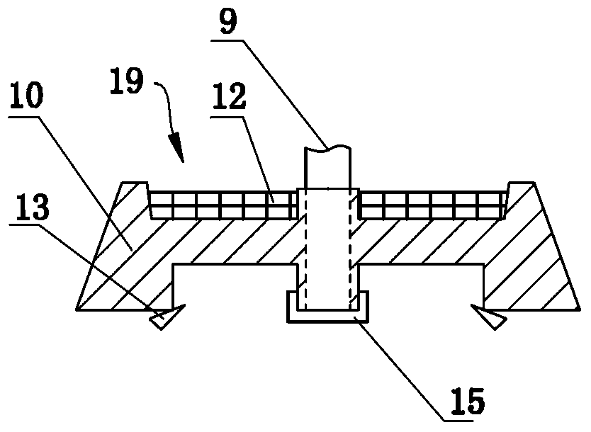
Image

Examples
Embodiment 1
[0081] Planed, milled, and end-faced carbon steel plates are available, and ground or polished stainless steel plates are available.
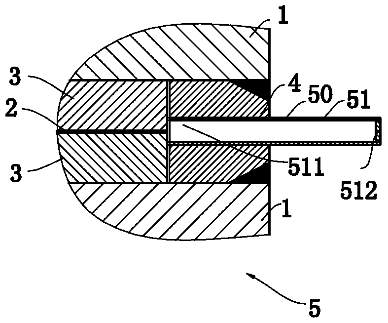
[0082] (1) Fix side plate 4 with width 50mm×20mm×length 5950mm by spot welding around a carbon steel plate with width 1500mm×thickness 100mm×length 6000mm, and then put a stainless steel plate with width 1400mm×thickness 10mm×length 5900mm into the In the cavity formed by the carbon steel plate and the side plate 4; then coat the release agent 2 on the stainless steel plate; then put another stainless steel plate with a width of 1400mm × thickness 10mm × length 5900mm; then stack another on the side plate 4 A carbon steel plate with a width of 1500mm×thickness 100mm×length 6000mm is spot-welded to fix another carbon steel plate with a width of 1500mm×thickness 100mm×length 6000mm and the side plate 4 to form the predecessor of the combined billet with a width of 1500mm×thickness 220mm×length 6000mm; then pressing The predecessor of the combined...
Embodiment 2
[0092] Planed, milled, and end-faced carbon steel plates are available, and ground or polished stainless steel plates are available.
[0093] (1) Fix side plate 4 with width 50mm×thickness 60mm×length 9950mm by spot welding around a carbon steel plate with width 2200mm×thickness 300mm×length 10000mm, and then put a stainless steel plate with width 2100mm×thickness 30mm×length 9900mm into the In the cavity formed by the carbon steel plate and the side plate 4; then coat the release agent 2 on the stainless steel plate; then put another stainless steel plate with a width of 2100mm × thickness 30mm × length 9900mm; then stack another on the side plate 4 A carbon steel plate with a width of 2200mm×thickness 300mm×length 10000mm is fixed by spot welding another carbon steel plate with a width of 2200mm×thickness 300mm×length 10000mm and a side plate 4 to form a combined blank precursor of width 2200mm×thickness 660mm×length 10000mm; then pressing The predecessor of the combined bla...
PUM
 Abstract
Description
Claims
Application Information