Fixed oxide fuel cell

a fuel cell and fixed oxide technology, applied in the field of fixed oxide fuel cells, can solve the problems of fuel gas and oxidant gas undesired flow out of manifolds, difficult for glass-made seal portions to follow the relatively great variation,

Inactive Publication Date: 2015-06-09
HONDA MOTOR CO LTD
View PDF7 Cites 0 Cited by
  • Summary
  • Abstract
  • Description
  • Claims
  • Application Information

AI Technical Summary

Benefits of technology

[0006]In view of the foregoing prior art problems, it is an object of the present invention to provide an improved fixed oxide fuel cell which can reliably prevent fuel gas and oxidant gas from flowing out from respective manifolds.
[0008]In the fixed oxide fuel cell of the present invention, the silver plate layers are provided, as seal portions, between the separators for sealing joints in the fuel gas and oxidant gas manifolds. With the silver plate layers provided as seal portions, the present invention can increase rigidity (toughness, tenacity, etc.) of the seal portions as compared to the case where the seal portions are formed of glass. Thus, even when the fixed oxide fuel cell of the present invention has varied relatively greatly in temperature, it can prevent the seal portions (silver plate layers) from being damaged due to the relative great temperature variation. In this way, the fixed oxide fuel cell of the present invention can reliably prevent fuel gas and oxidant gas from flowing out of the fuel gas and oxidant gas manifolds.
[0011]This is why the silver plate layers are provided on the seal surfaces of the communication section in the present invention. Namely, in the present invention, silver plating is provided only on each of the seal surfaces of the communication sections; namely, the silver plating can be provided only on portions that require the silver plating (i.e., only on the seal portions of the fuel gas and oxidant gas manifolds). In this way, it is possible to minimize the amount of silver used.
[0012]Further, in the present invention, the communication section only has the communicating hole constituting the fuel gas or oxidant gas manifold. Thus, when providing the silver plating on the seal surfaces of the communication section, it is not necessary to cover or mask the other gas passages (gas flow paths) with a masking member. Namely, because only the communicating holes constituting the manifolds have to be covered or masked with a masking member, the present invention permits simplification in shape of the masking member.
[0013]Preferably, the silver plate layer is formed for sealing between the seal surface of the communication section and the separator, by: placing the communication section between the separators after providing silver plating on the seal surface of the communication section; applying a predetermined load to the separators and the communication section; and melting the silver plating at a predetermined temperature. Thus, with the present invention, it is possible to appropriately seal between the separator and the seal surface of the communication section, with the predetermined load, which is to be applied to the separators and the communication section, kept at a low level. By thus limiting the predetermined load, which is to be applied to the separators and the communication section, to a low level range, the present invention can advantageously reduce a size of facilities for forming the silver plating.

Problems solved by technology

Therefore, when the fixed oxide fuel cell has varied relatively greatly in temperature, for example, it is difficult for the glass-made seal portions to follow the relatively great variation.
As a consequence, the glass-made seal portions might be damaged due to the relatively great variation of the fuel cell, so that the fuel gas and oxidant gas might undesirably flow out from the manifolds.

Method used


Image

  • Fixed oxide fuel cell
  • Fixed oxide fuel cell
  • Fixed oxide fuel cell

Examples


Embodiment Construction

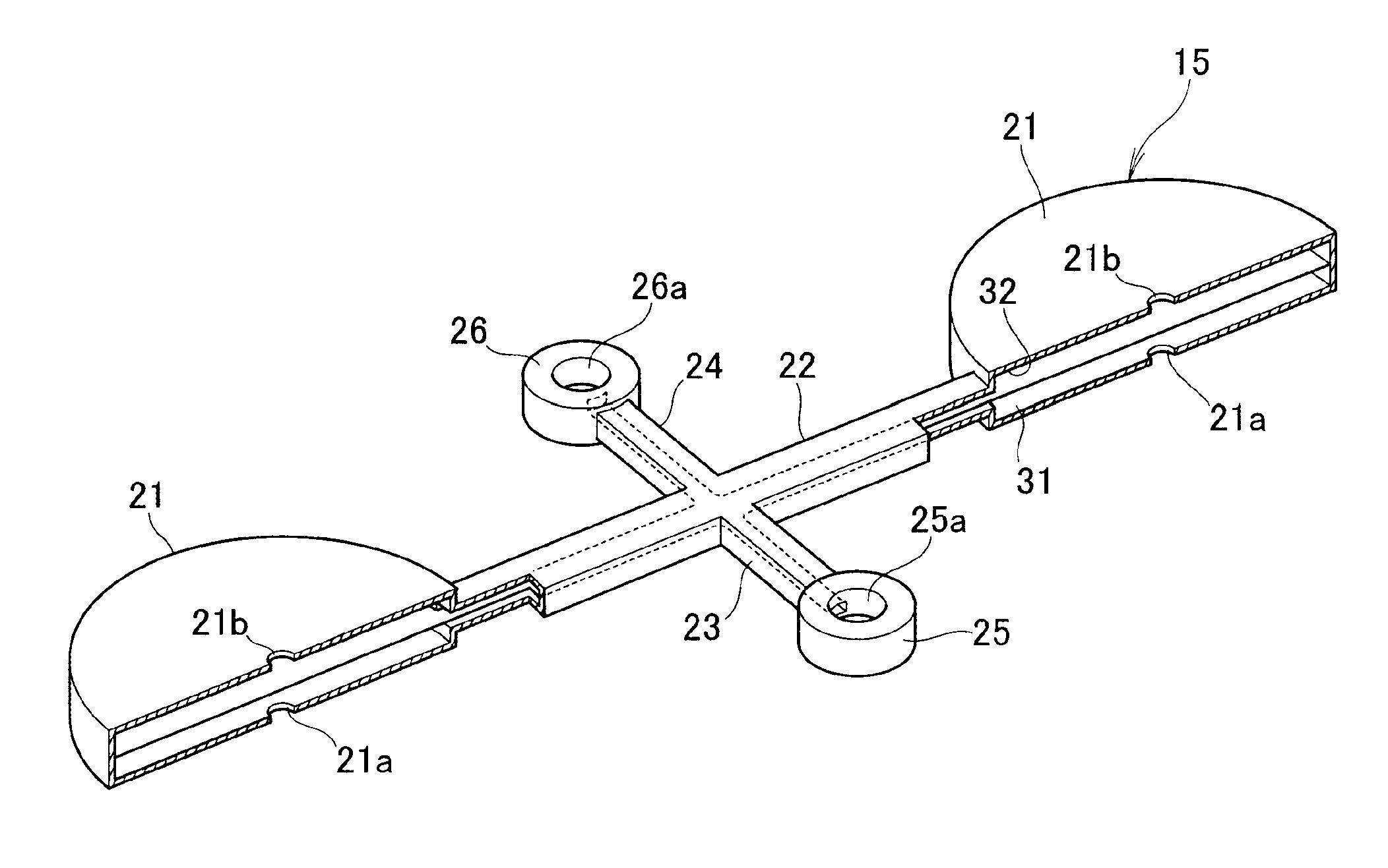
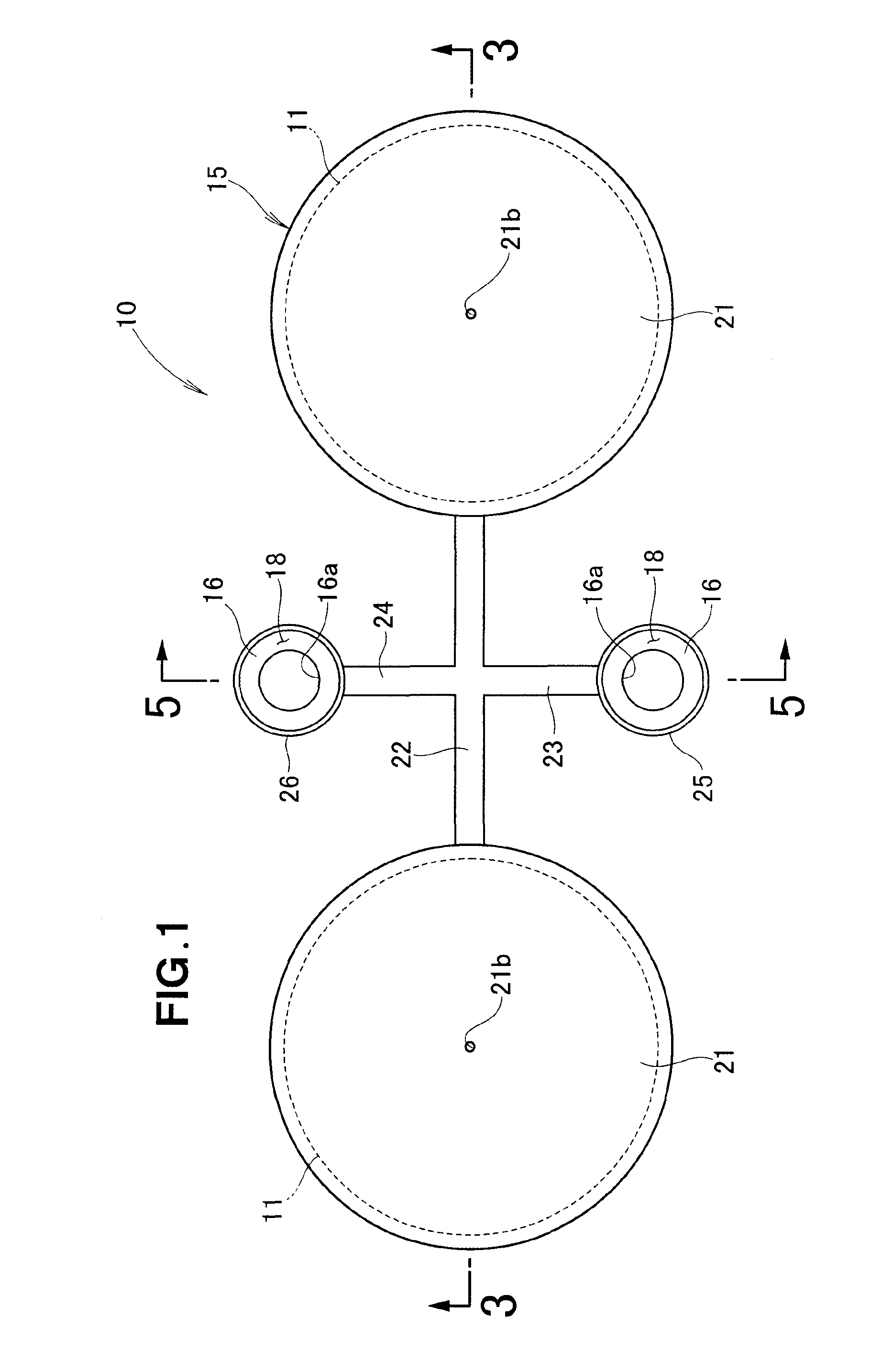
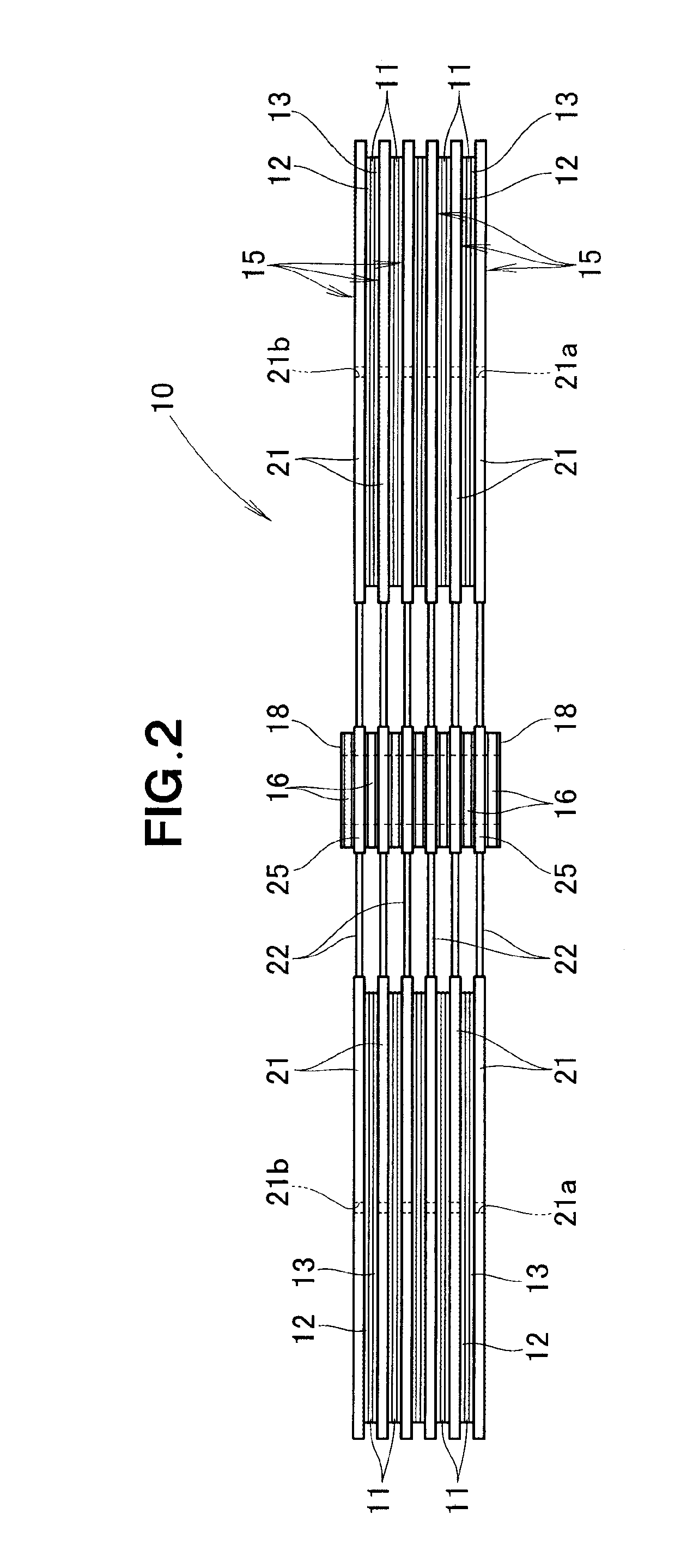
[0026]Reference is now taken to FIG. 1 showing, in plan, an embodiment of a fixed oxide fuel cell, FIG. 2 is a side view of the fixed oxide fuel cell shown in FIG. 1, and FIG. 3 is a sectional view taken along the 3-3 line of FIG. 1. As shown in FIGS. 1 and 2, the fixed oxide fuel cell 10 comprises a stack of: a plurality of membrane electrode assemblies (MEAs) 11; a plurality of pairs of current collectors 12 and 13, each of the pairs disposed over the opposite surfaces 11a and 11b (see FIG. 3) of one of the MEAs 11; a plurality of separators 15, every adjoining two of them disposed over one of the pairs of current collectors 12 and 13; a plurality of insulating communication sections 16 each disposed between the separators 15; and a plurality of silver plate layers 18 each provided on one of the insulating communication sections 16 to seal between the one insulating communication sections 16 and one of the separators 15 adjoining the one insulating communication sections 16.

[0027]...


PUM

PropertyMeasurementUnit
thicknessaaaaaaaaaa
temperature T1aaaaaaaaaa
temperatureaaaaaaaaaa

Abstract

A fixed oxide fuel cell includes: a plurality of separators each having first and second opening portions, the separators being stacked such that a membrane electrode assembly is interposed between the separators and that the first opening portions are aligned coaxially in communication with each other to constitute a fuel gas manifold while the second opening portions are aligned coaxially in communication with each other to constitute an oxidant gas manifold, fuel gas and oxidant gas being supplied to the membrane electrode assembly via the fuel gas and oxidant gas manifolds; and silver plate layers provided between the separators for sealing joints in the fuel gas and oxidant gas manifolds.

Description

FIELD OF THE INVENTION[0001]The present invention relates to fixed oxide fuel cells which include manifolds formed by separators sandwiching therebetween a membrane electrode assembly, and in which fuel gas and oxidant gas are supplied from the manifolds to the membrane electrode assembly.BACKGROUND OF THE INVENTION[0002]Fixed oxide fuel cells are known which are constructed to provide desired outputs by means of a stack of a multiplicity of fuel cells. In each of the fuel cells, separators are provided on the opposite surfaces of a membrane electrode assembly (also referred to as “MEA”), i.e. sandwich the membrane electrode assembly, via current collectors. With the current collectors interposed between the separators and the MEA, it is possible to secure given contact areas between the MEA and the separators while allowing manufacturing errors of the MEA and separators.[0003]In each of the separators are formed gas flow paths (or gas passages) for directing fuel gas and oxidant ga...

Claims


Application Information

Patent Timeline
Patent Type & Authority Patents(United States)
IPC IPC(8): H01M8/04H01M8/02H01M8/24H01M8/12
CPCH01M8/12H01M8/0282H01M8/24H01M8/2485H01M8/249H01M2008/1293Y02E60/521Y02E60/525H01M8/2483Y02E60/50H01M8/243
Inventor USHIJIMA, TERUYUKI
Owner HONDA MOTOR CO LTD
Why Eureka
Try Eureka