Outboard engine unit

a technology for outboard engines and gear boxes, which is applied in the direction of propulsive elements, marine propulsion, vessel construction, etc., can solve the problems of lowering the capability (sliding travel capability) of the outboard engine unit, and the difficulty of retaining lubricant oil within the gear chamber through sealing parts, so as to increase the size of the gear case and enhance the durability of the power transmission system

Active Publication Date: 2014-08-26
HONDA MOTOR CO LTD
View PDF6 Cites 0 Cited by
  • Summary
  • Abstract
  • Description
  • Claims
  • Application Information

AI Technical Summary

Benefits of technology

[0009]An improved outboard engine unit is provided which can achieve an enhanced durability of the power transmission system, particularly the gear mechanism, without increasing the size of the gear case.
[0011]The lubricant oil having lubricated the bearing is returned back to the gear chamber by means of the circulation section and the oil storage chamber and return passage. Thus, even where a power transmission system, particularly the gear mechanism, of the outboard engine unit is increased in size, the outboard engine unit can smoothly circulate the lubricant oil without increasing the size of the gear chamber in accordance with the increased size of the gear mechanism. By the smooth circulation of the lubricant oil, the inner pressure of the drive shaft chamber and gear chamber can be maintained suitable, so that it is possible to reliably prevent the lubricant oil from flowing out of the drive shaft chamber and gear chamber. Further, by increasing the size of the power transmission system, particularly the gear mechanism, it is possible to increase the rigidity (strength) of the gear mechanism and thereby increase the durability of the power transmission system.
[0012]Preferably, the outboard engine unit further comprises: a supply passage having an inlet portion opening to the gear chamber, the supply passage directing the lubricant oil of the gear chamber to the bearing via the inlet portion; a guide protrusion projecting into the gear chamber from a far-side part (or downstream part), in a rotation direction of the gear mechanism, of the inner peripheral surface around and adjacent to the inlet portion of the supply passage, for guiding the lubricant oil of the gear chamber toward the inlet portion of the supply passage. With the guide protrusion guiding the lubricant oil of the gear chamber toward the inlet portion of the supply passage, the lubricant oil can be efficiently guided to the drive shaft chamber to thereby even more efficiently lubricate the bearing.
[0013]Preferably, the outboard engine unit further comprises a guide passage communicating between the oil storage chamber and the drive shaft chamber for guiding the lubricant oil, having lubricated the bearing, to the oil storage chamber. Thus, the oil storage chamber is allowed to be in communication with the drive shaft chamber via the guide passage even where the oil storage chamber is located at a considerable distance from the drive shaft chamber. Therefore, the portion for providing therein the oil storage chamber can be chosen from a relatively wide range of choices, which can thus achieve an enhanced design freedom.
[0014]Further, preferably, in the outboard engine unit, the drive shaft chamber and the gear chamber are both provided in a gear case, and the oil storage chamber is provided in an unusable portion of the gear case. If the shaft chamber and the gear chamber are increased in size, the gear case would also increase in size. However, because the gear case is a component part immersed in seawater during sliding travel of a watercraft body, it is preferable, in view of resistance of the seawater, that the gear case be not increased in size. Thus, in the outboard engine unit, the gear case, which is formed by casting, has a hollow portion formed in an unusable portion of the gear case, and the hollow portion formed in the unusable portion of the gear case is used as the oil storage chamber. Here, the “unusable portion” is a portion of the gear case that cannot be used as the drive shaft chamber or gear chamber. Because the hollow portion formed in the unusable portion of the gear case is used as the oil storage chamber, the outboard engine unit can maintain a suitable inner pressure of the shaft chamber and the gear chamber without increasing the size of the gear case. Further, the outboard engine unit can provide the oil storage chamber without newly securing a particular portion for providing therein the oil storage chamber and thus without increasing the size of the gear case. Because the size of the gear case does not have to be increased, the outboard engine unit can prevent resistance of seawater from becoming great during sliding travel of the watercraft body, so that an enhanced capability (sliding travel capability) of the outboard engine unit can be secured.

Problems solved by technology

Hence, as the lubricant oil is circulated to lubricate the taper roller bearing, inner pressure of the gear chamber would increase so that it becomes difficult to retain the lubricant oil within the gear chamber by means of a sealing member.
However, if the size of the gear case is increased like this, resistance of seawater would increase during sliding travel of the hull or body of the watercraft, which would result in a cause of lowered capability (sliding travel capability) of the outboard engine unit.

Method used


Image

  • Outboard engine unit
  • Outboard engine unit
  • Outboard engine unit

Examples


Embodiment Construction

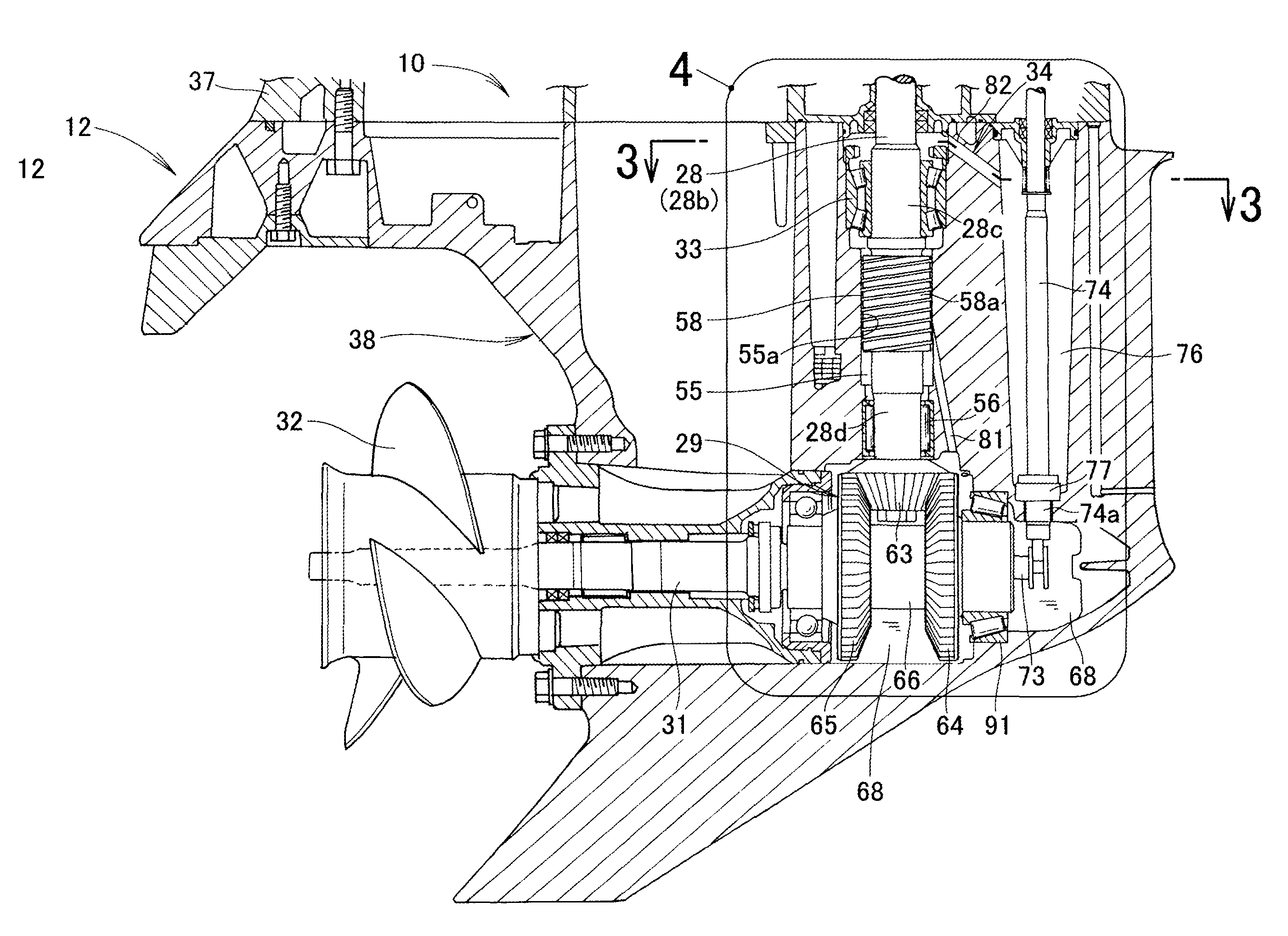
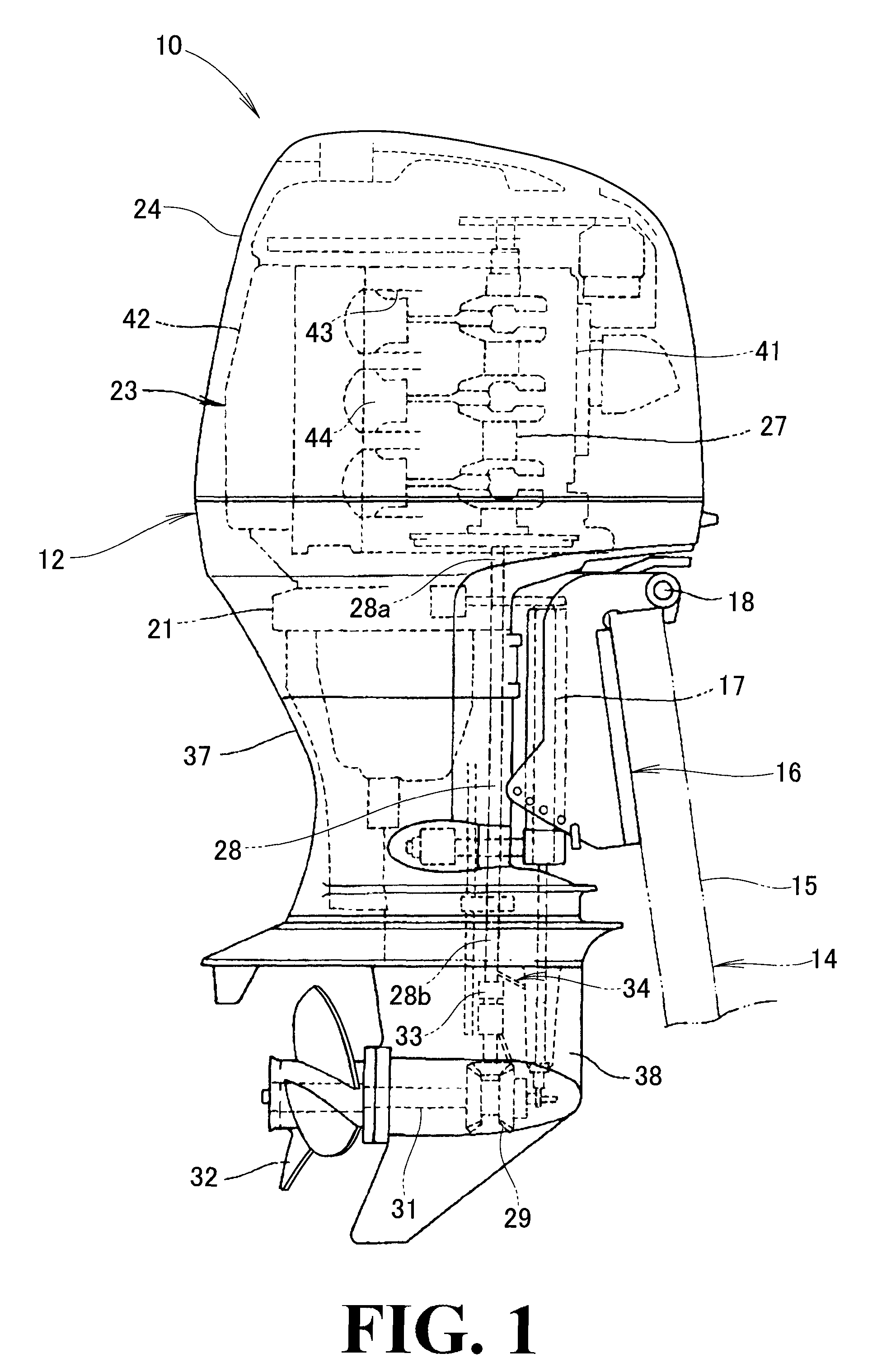
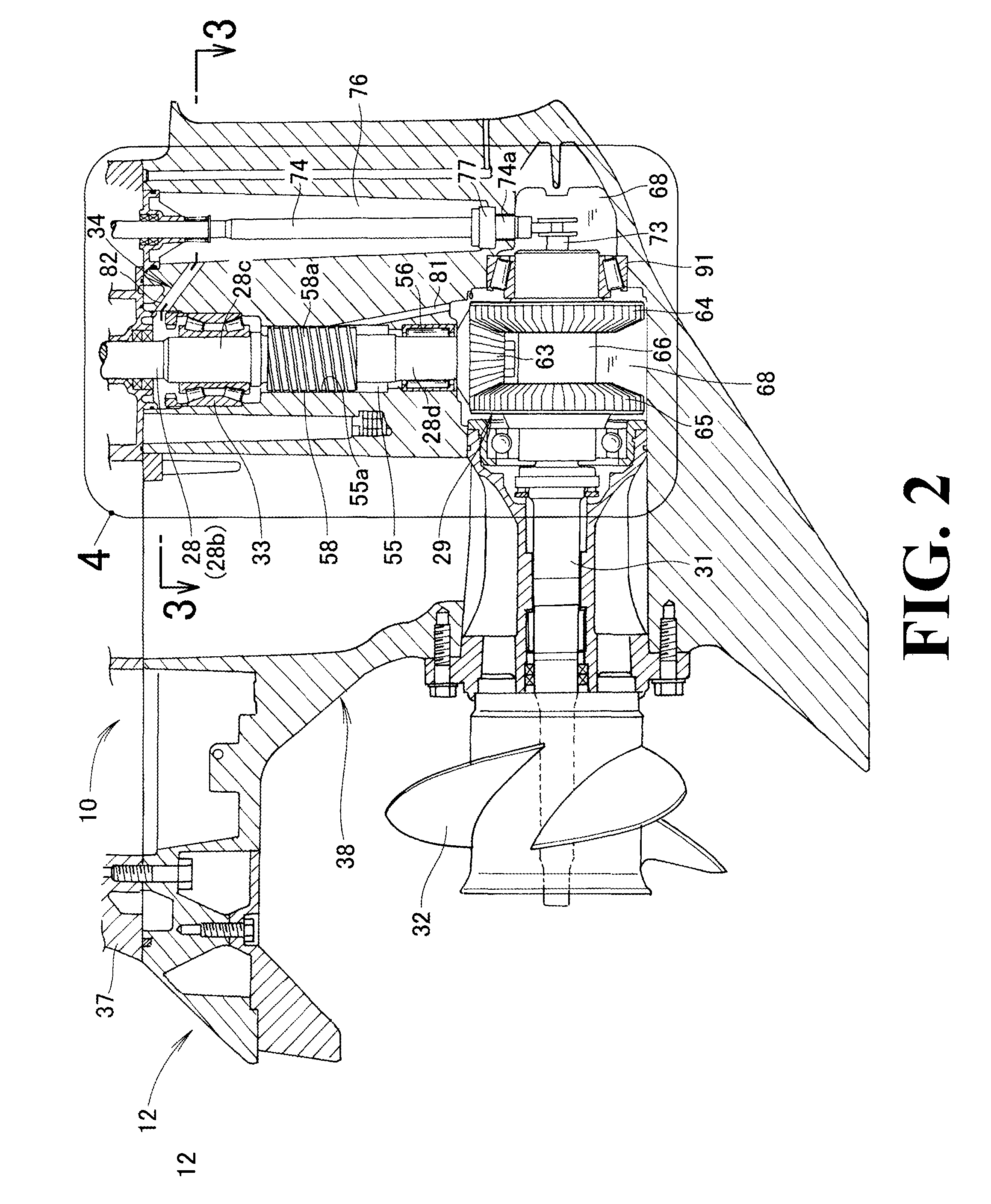
[0028]Reference is now made to FIG. 1 showing in side elevation an outboard engine unit 10 according to an embodiment of the present invention. As shown in FIG. 1, the outboard engine unit 10 comprises an outboard engine unit body 12, and a mounting section 16 provided on the outboard engine unit body 12 and detachably attachable to a hull or body (more specifically, stern 15) of a watercraft. The mounting section 16 includes a swivel shaft 17 about which the outboard engine unit body 12 is pivotable in a left-right or horizontal direction, and a tilt shaft 18 about which the outboard engine unit body 12 is pivotable in an up-down or vertical direction.

[0029]The outboard engine unit body 12 includes: a mount case 21 provided on the mounting section 16; an engine 23 mounted on an upper portion of the mount case 21; an engine cover 24 covering the engine 23; a drive shaft 28 having an upper end portion 28a connected to a crank shaft 27 of the engine 23; a gear mechanism 29 to which ro...


PUM


Abstract

An outboard engine unit, where a drive shaft is connected to an engine and rotatably supported in a drive shaft chamber via a bearing and where a gear mechanism for transmitting rotation of the drive shaft to a propeller shaft is accommodated in a gear chamber, includes: a lubricant circulation section for returning lubricant oil, having lubricated the bearing, back to the gear chamber; an oil storage chamber for receiving the lubricant oil having lubricated the bearing; and a return passage communicating the oil storage chamber with the gear chamber. The lubricant oil guided to the oil storage chamber is returned back to the gear chamber via the return passage.

Description

CROSS-REFERENCE TO RELATED APPLICATIONS[0001]The present application claims priority under 35 U.S.C. §119 to Japanese Patent Application No. 2011-189006, filed Aug. 31, 2011, entitled “OUTBOARD ENGINE UNIT”. The contents of this application are incorporated herein in their entirety.TECHNICAL FIELD[0002]The present invention relates to outboard engine units which include a drive shaft connected to an engine and rotatably supported in a drive shaft chamber via a bearing, and in which rotation of the drive shaft is transmitted to a propeller shaft via a gear mechanism.BACKGROUND OF THE INVENTION[0003]Generally, in outboard engine units, a drive shaft for transmitting rotation of an engine extends vertically, a pair of bevel gears meshingly engage with a pinion (i.e., pinion bevel gear) provided on a lower end portion of the vertical drive shaft, and a propeller shaft is connected to the bevel gears via a clutch (dog clutch). The pinion, the pair of bevel gears and the clutch are accomm...

Claims


Application Information

Patent Timeline
Patent Type & Authority Patents(United States)
IPC IPC(8): B63H20/20B63H21/38
CPCB63H21/38B63H20/20
Inventor YOSHIGASAKI, TSUYOSHIISHIKAWA, TOMOAKIKATAGIRI, NOBUCHIKA
Owner HONDA MOTOR CO LTD
Why Eureka
Try Eureka