Plug cap

a plug and plug technology, applied in the direction of sparking plugs, machine/engines, coupling device connections, etc., can solve the problem of not being able to mold the outer portion of the terminal body, and achieve the effect of preventing water ingress reliably

Inactive Publication Date: 2014-10-07
HONDA MOTOR CO LTD
View PDF28 Cites 1 Cited by
  • Summary
  • Abstract
  • Description
  • Claims
  • Application Information

AI Technical Summary

Benefits of technology

[0019]Further, as described above, in terms of manufacture, a parting line, which extends in a longitudinal direction, is generally formed on the outer peripheral surface of the terminal body. On the other hand, the inner peripheral surface of the terminal body becomes smooth so that a parting line extending in the longitudinal direction is not formed. That is, according to Structure 1, the protrusions come into press contact with the inner peripheral surface of the terminal body having a smooth shape by the insertion of the spark plug or the like. Accordingly, it is possible to make the protrusions come into close contact with the terminal body without clearance over the entire area in the circumferential direction of the terminal body. As a result, it is possible to effectively suppress the ingress of water from the gap between the terminal body and the rubber member. Consequently, it is possible to more reliably prevent leakage of current.
[0047]According to Structure 6, the reduced-diameter portion, which is formed in a tapered shape toward the end portion opposite to the end portion of the terminal body on which the rubber member including the outer cylindrical portion is mounted, is formed at the leading end portion of the outer cylindrical portion. Accordingly, it is possible to prevent water from standing between the terminal body and the leading end portion of the outer cylindrical portion as much as possible. Consequently, it is possible to more reliably prevent the ingress of water.

Problems solved by technology

Accordingly, when the above-mentioned terminal body is formed, it is not possible to mold the outer portion of the terminal body by only one mold.

Method used


Image

  • Plug cap
  • Plug cap
  • Plug cap

Examples


Embodiment Construction

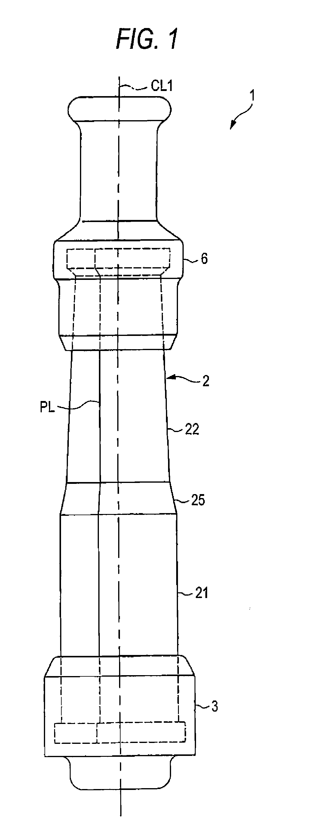
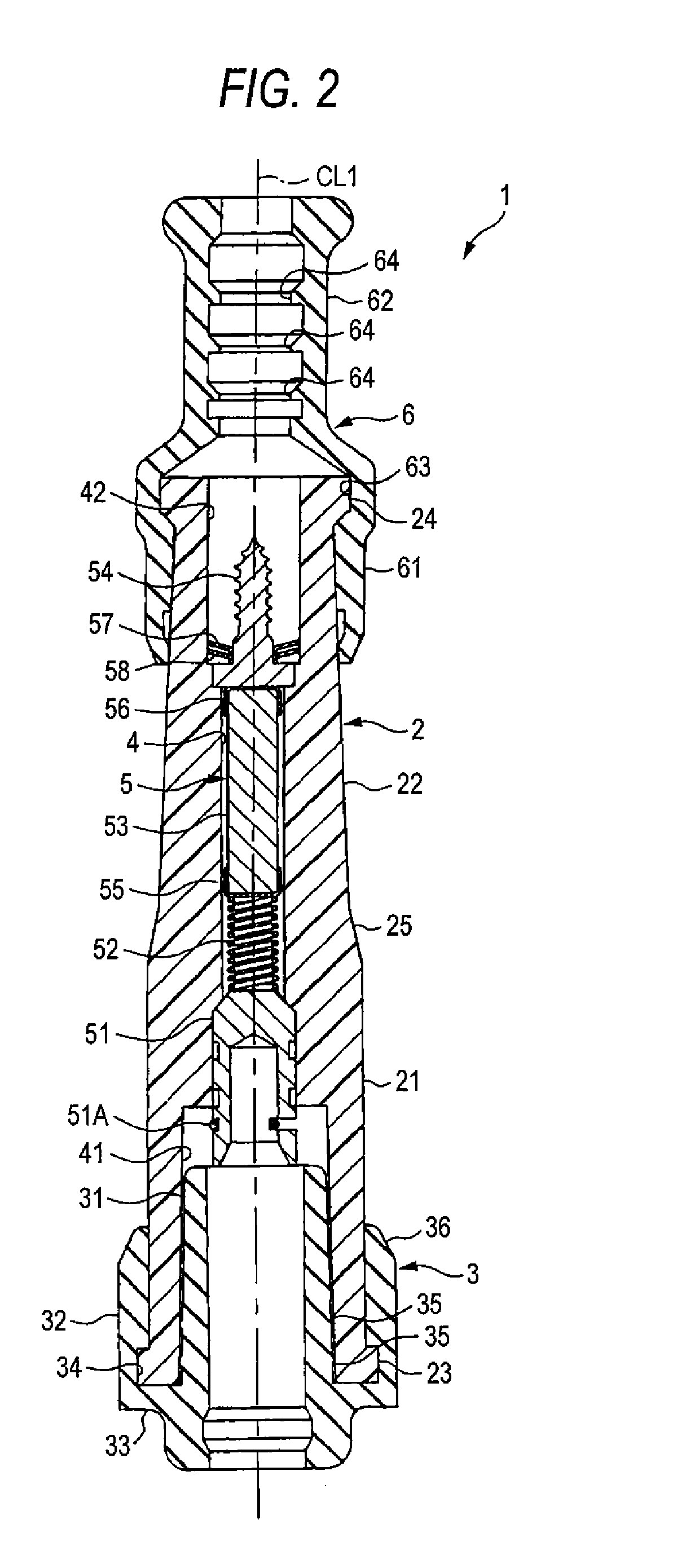
[0057]An embodiment will be described below with reference to the drawings. FIG. 1 is a front view of a plug cap 1, and FIG. 2 is a cross-sectional view of the plug cap 1. Meanwhile, in FIGS. 1 and 2, the direction of an axis CL1 of the plug cap 1 is referred to as a vertical direction, the lower side of the plug cap is referred to as one end-side of the plug cap 1, and the upper side of the plug cap is referred to as the other end-side of the plug cap 1.

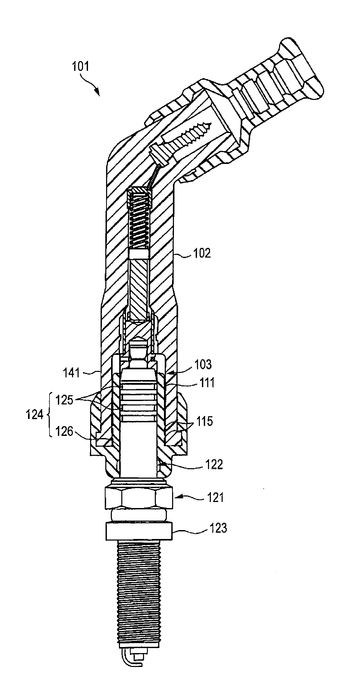
[0058]The plug cap 1 includes a terminal body 2 that has a cylindrical shape, a plug-side rubber member 3 (which corresponds to a rubber member in the invention) that is mounted on one end of the terminal body, and the like.

[0059]The terminal body 2 is formed in a straight shape, and is made of a resin (for example, a phenol resin) that has heat resistance and voltage resistance. Further, the outer portion of the terminal body 2 includes a one end-side body portion 21 that has a relatively large diameter and the other end-side body ...


PUM


Abstract

One object of the invention is to provide a plug cap that more reliably prevents the leakage of current by suppressing the ingress of water from a gap between a terminal body and a rubber member.A plug cap 1 includes an electrical connection portion 5 that electrically connects a spark plug to a plug cord, a terminal body 2 that is provided on the outer periphery of the electrical connection portion 5, and a cylindrical rubber member 3 which is mounted on at least one of one end portion and the other end portion of the terminal body 2 and into which the spark plug or the like is inserted. The terminal body 2 includes a one end-side insertion portion 41 which is formed at one end of the terminal body and into which the spark plug is inserted and the other end-side insertion portion 42 which is formed at the other end of the terminal body and into which the plug cord is inserted. The rubber member 3 includes an inner cylindrical portion 31 that is inserted into the one end-side insertion portion 41 or the other end-side insertion portion 42, and a cylindrical outer cylindrical portion 32 that is positioned close to the outer periphery of the inner cylindrical portion 31. The inner cylindrical portion 31 includes annular protrusions 35 that come into contact with the inner peripheral surface of the terminal body 2.

Description

TECHNICAL FIELD[0001]The present invention relates to a plug cap that electrically connects a spark plug to a plug cord.BACKGROUND ART[0002]A plug cap electrically connects a spark plug, which is mounted on an internal combustion engine, to a plug cord, which extends from an ignition coil or a distributor, in order to apply a high voltage to the spark plug. As the plug cap, there is known a plug cap including a terminal body which is made of a resin and of which at least both end portions have a cylindrical shape and a cylindrical rubber member that is mounted on an end portion of the terminal body. The rubber member includes a cylindrical inner cylindrical portion, a cylindrical outer cylindrical portion that is disposed close to the outer periphery of the inner cylindrical portion with a predetermined gap interposed therebetween, and a connecting portion that connects the inner cylindrical portion to the outer cylindrical portion. An end portion of the terminal body is fitted betw...

Claims


Application Information

Patent Timeline
Patent Type & Authority Patents(United States)
IPC IPC(8): H01R13/52F02P13/00H01T13/06
CPCF02P13/00H01T13/06
Inventor FUMA, TOMOHIROOHTA, JUNPEIKITAMURA, RYOHEIYAMAMOTO, TAKAOSONODA, YUTAKA
Owner HONDA MOTOR CO LTD
Why Eureka
Try Eureka