Method for manufacturing a coating instrument

a manufacturing method and coating technology, applied in packaging foodstuffs, packaging goods types, transportation and packaging, etc., can solve the problem of space not being formed in some cases, and achieve the effect of preventing leakage of coating materials

Active Publication Date: 2016-03-15
TOKIWA CORP
View PDF4 Cites 4 Cited by
  • Summary
  • Abstract
  • Description
  • Claims
  • Application Information

AI Technical Summary

Benefits of technology

[0005]Here, in the above described method for manufacturing a coating instrument, as described above, since the space is formed on the tip end side in the filling region by the elastic recovery of the coating portion, the space cannot be sufficiently formed in some cases depending on a shape of the coating portion, for example. Thus, in the recent methods for manufacturing a coating instrument, securing of a space of a certain amount on the tip end side in the filling region so as to reliably prevent leakage of the coating material from the discharge outlet is in demand.
[0006]Thus, the one aspect of the present invention has an object to provide a method for manufacturing a coating instrument which can reliably prevent leakage of the coating material from the discharge outlet.
[0008]In the method for manufacturing according to the one aspect of the present invention, after the air is fed from the discharge outlet into the filling region in which the coating material is filled, the body portion is assembled to the filling member. As a result, a certain amount of space can be reliably ensured on the tip end side in the filling region, and leakage of the coating material from the discharge outlet can be reliably prevented by this certain amount of space.
[0010]The discharge outlet or the tip end side of the filling region may have a predetermined diameter such that the coating material filled in the filling region in a molten state does not flow down from the discharge outlet. In this case, the coating material can be reliably filled in the filling region. Moreover, since the coating material does not flow down from the discharge outlet, the air can be effectively fed from the discharge outlet.

Problems solved by technology

Here, in the above described method for manufacturing a coating instrument, as described above, since the space is formed on the tip end side in the filling region by the elastic recovery of the coating portion, the space cannot be sufficiently formed in some cases depending on a shape of the coating portion, for example.

Method used


Image

  • Method for manufacturing a coating instrument
  • Method for manufacturing a coating instrument
  • Method for manufacturing a coating instrument

Examples


Embodiment Construction

[0030]Hereinafter, an embodiment according to an aspect of the present invention will be described in detail by referring to the attached drawings. In the following explanation, the same reference numerals are given to the same or corresponding elements, and duplicated explanation will be omitted.

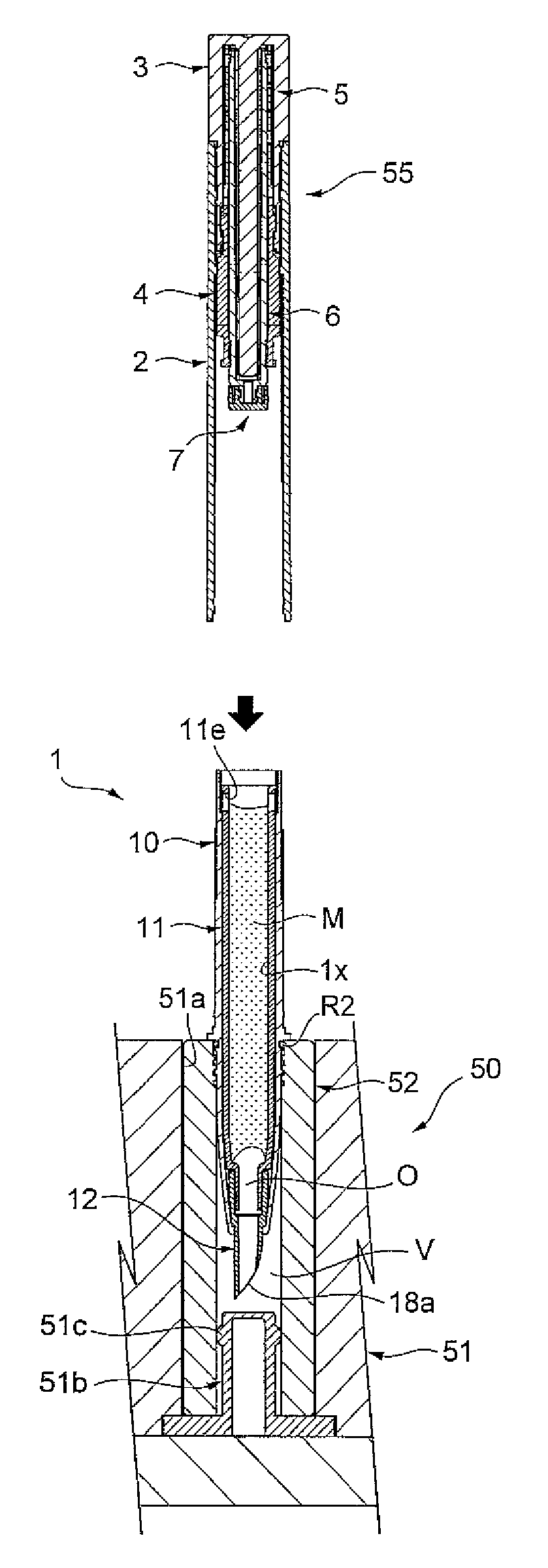
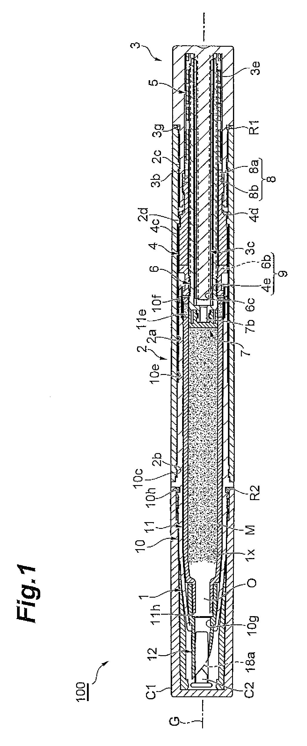
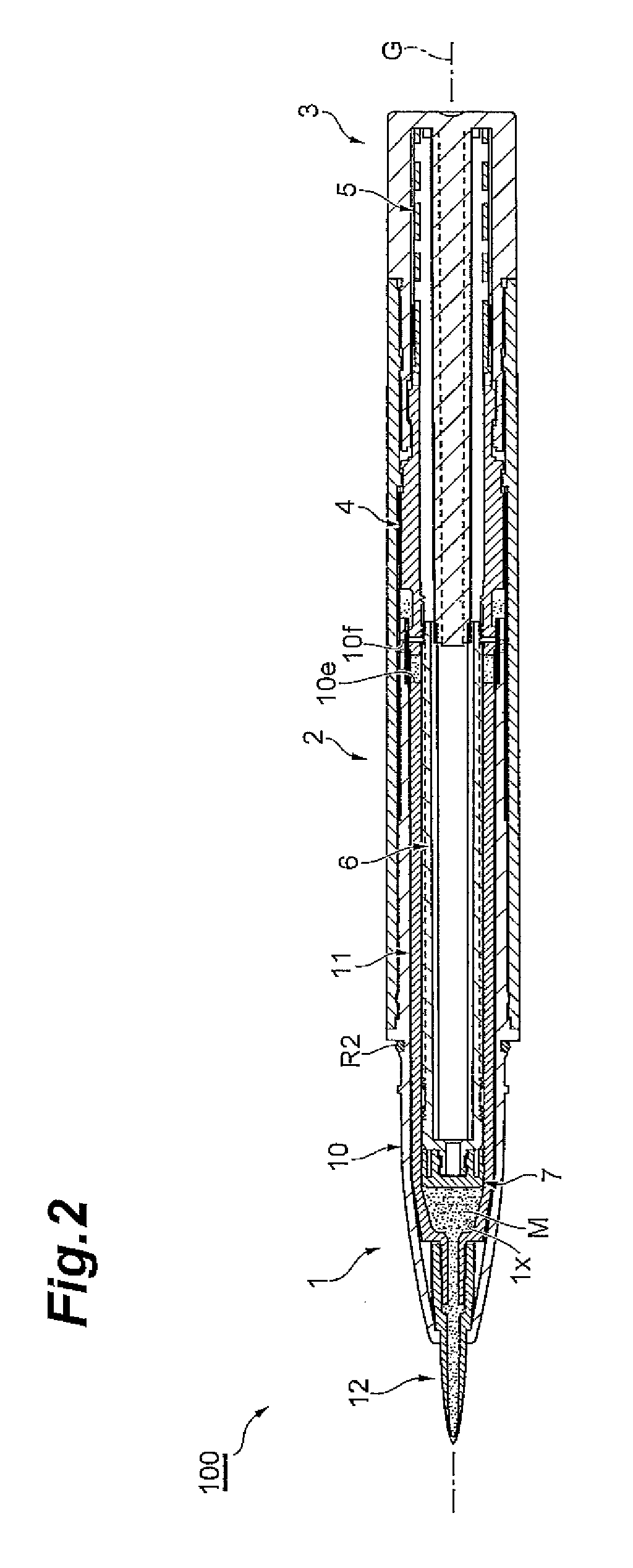
[0031]FIG. 1 is a longitudinal sectional side view illustrating an initial state of a coating instrument according to an embodiment, FIG. 2 is a longitudinal sectional side view illustrating a state of an advance limit of a moving body in the coating instrument, FIG. 3 is an exploded perspective view illustrating the coating instrument in a partially sectional view, and FIG. 4 is a sectional view illustrating an essential part in the coating instrument in FIG. 1 in an enlarged manner. FIG. 2 is a longitudinal sectional view having a longitudinal sectional position in FIG. 1 at a position different by 90°. As illustrated in FIGS. 1 to 3, a coating instrument 100 of this embodiment is to disc...


PUM

PropertyMeasurementUnit
temperatureaaaaaaaaaa
speedaaaaaaaaaa
depthaaaaaaaaaa

Abstract

There is provided a method for manufacturing a coating instrument provided with a filling member having a filling region in which a coating material is filled and a body portion including an extruding portion inserted inside so as to be brought into close contact with the filling member and constituting a rear end of the filling region, in which the coating material is discharged from a discharge outlet on a tip end side of the filling member by advance of the extruding portion, including a step of filling the coating material into the filling region of the filling member from behind in a state in which a front side of the filling member is located below the rear side, a step of feeding a predetermined amount of air from the discharge outlet into the filling region so that a space is formed on the tip end side in the filling region after the coating material is filled, and a step of assembling the body portion to the filling member after the air is fed.

Description

BACKGROUND OF THE INVENTION[0001]1. Field of the Invention[0002]An aspect of the present invention relates to a method for manufacturing a coating instrument used by extruding a coating material.[0003]2. Related Background Art[0004]As a prior-art method for manufacturing a coating instrument, a method described in Japanese Patent Laid-Open No. 2006-136774, for example, is known. In the manufacturing method described in Japanese Patent Laid-Open No. 2006-136774, when a coating portion is elastically recovered after a coating filler (coating material) is filled in a filling region in a state in which the coating portion of a filling member is recessed, a space is formed on a tip end side including a discharge outlet in the filling region. As a result, even if the coating material is swollen or the like due to a temperature change or an air pressure change, leakage of the coating material from the discharge outlet can be prevented.SUMMARY OF THE INVENTION[0005]Here, in the above descri...

Claims


Application Information

Patent Timeline
Patent Type & Authority Patents(United States)
IPC IPC(8): B65D83/00B43K15/00A45D34/04B43K11/00
CPCB43K15/00B43K11/00A45D2200/055B65D83/0005Y10T29/49401A45D2200/1072
Inventor TANI, YOSHIKAZU
Owner TOKIWA CORP
Why Eureka
Try Eureka