Module for a fuel cell arrangement

a fuel cell and module technology, applied in the direction of fuel cell details, cell components, electrochemical generators, etc., can solve the problems of overflow of cooling fluid or fuel cell gases, increased electrical resistance, and difficulty in carrying out quality assurance and inspection measures on sealing arrangements, so as to achieve reliable prevention of leakage

Active Publication Date: 2012-01-31
CARL FREUDENBERG KG
View PDF16 Cites 3 Cited by
  • Summary
  • Abstract
  • Description
  • Claims
  • Application Information

AI Technical Summary

Benefits of technology

[0004]An object of the present invention is, therefore, to devise a module for a fuel cell arrangement which will make it possible to reliably prevent leakage between the plates.

Problems solved by technology

It is disadvantageous in this context that shrinkage processes occurring in the sealing element can lead to local leakage between the plates, which can cause cooling fluid or fuel cell gases to overflow, or that sealing material is pressed into the intermediate space between the plates, thereby resulting in an increased electrical resistance due to a gap effect.
It is difficult to carry out quality assurance and inspection measures on sealing arrangements of this kind, since a non-destructive examination of the sealing site is not possible.

Method used


Image

  • Module for a fuel cell arrangement
  • Module for a fuel cell arrangement
  • Module for a fuel cell arrangement

Examples


Embodiment Construction

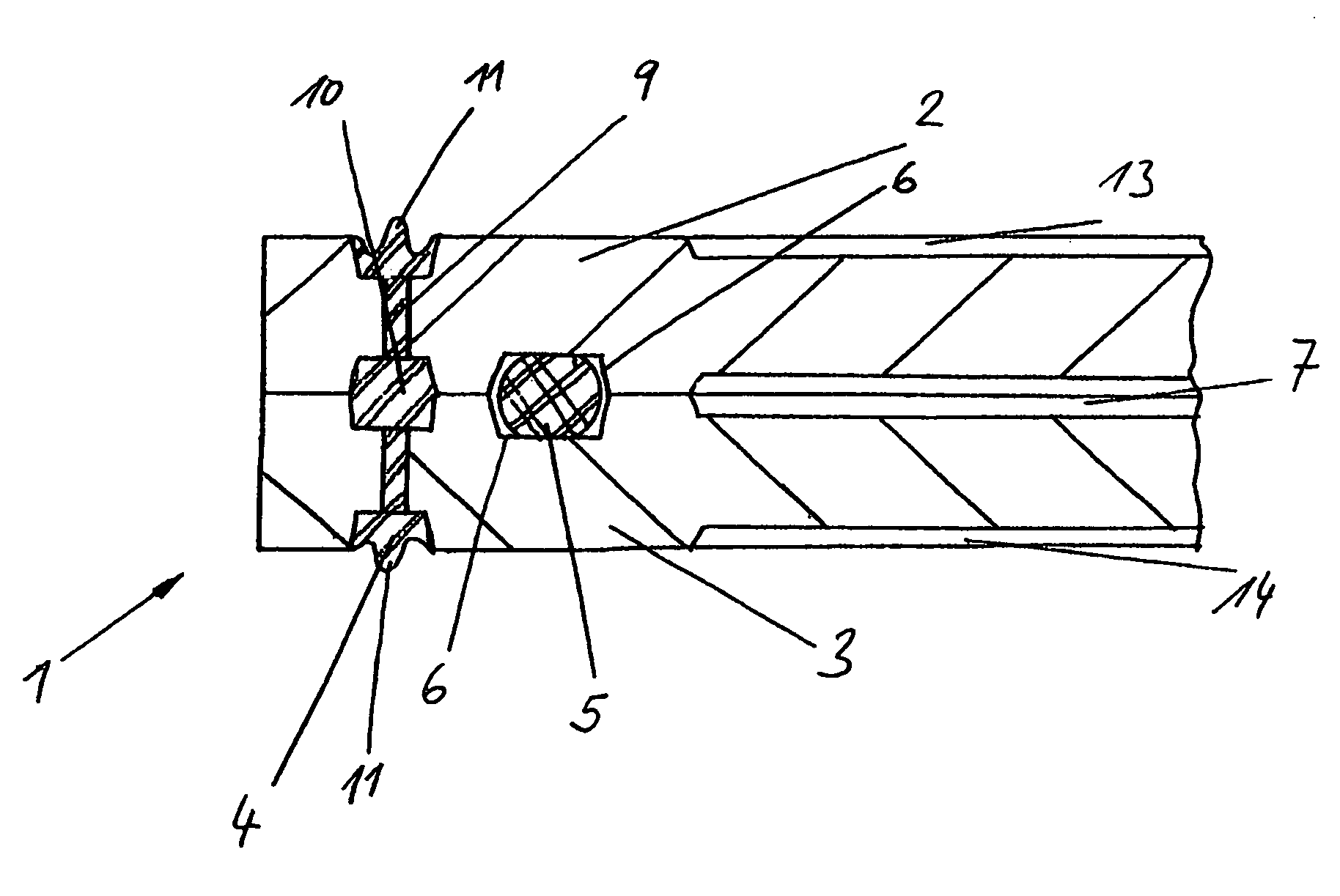
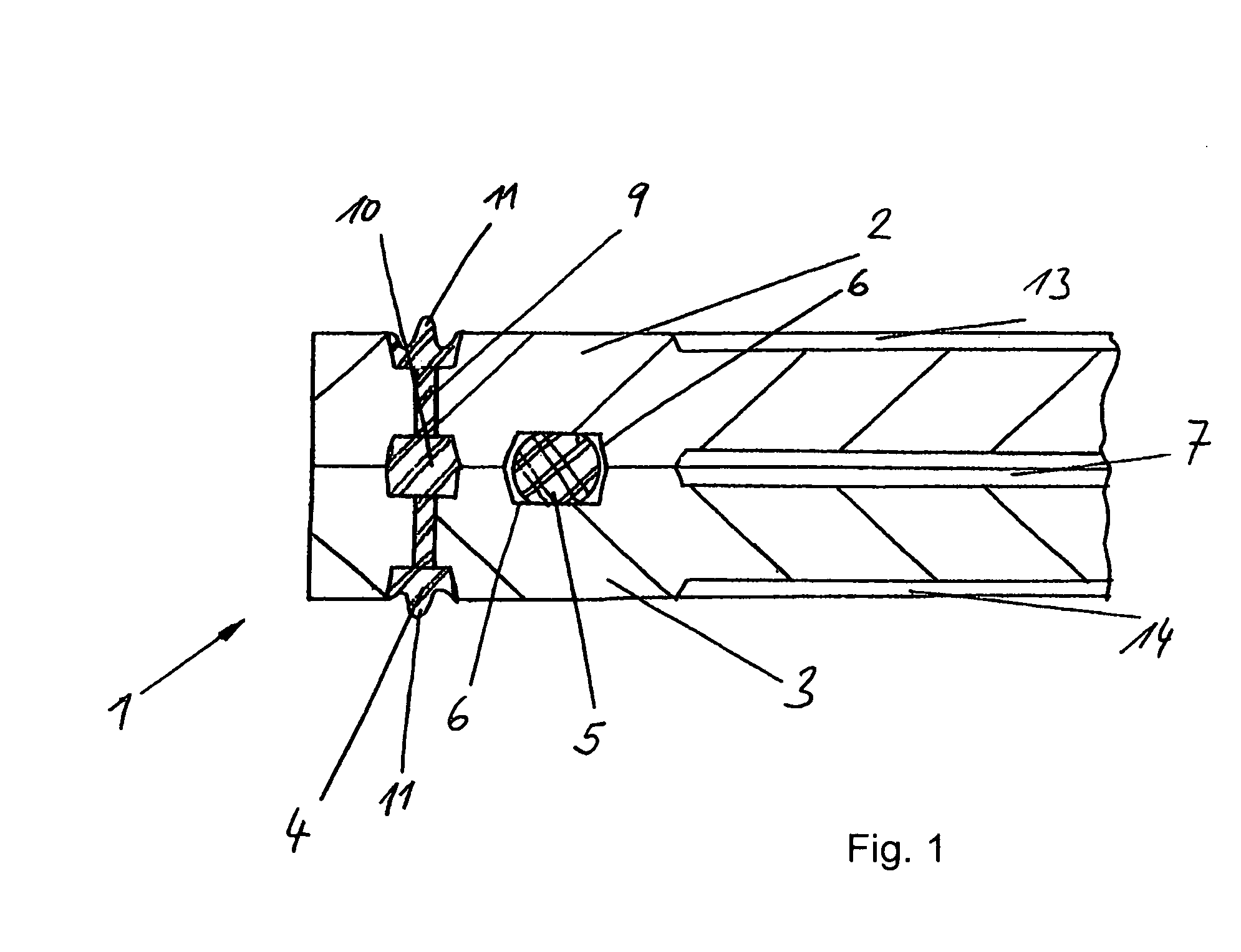
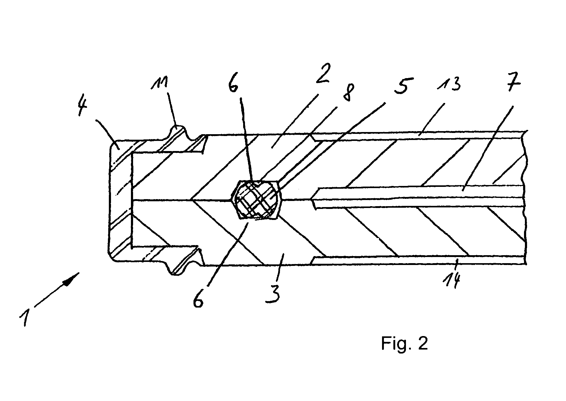
[0029]The figures each show a module 1 for a fuel cell arrangement, which, in these design variations, is a PEM fuel cell. Module 1 is composed of two plates 2, 3 which are configured in the form of a stack and are partially joined to one another by a sealing element 4. For that purpose, plates 2, 3 have elongated hole-type openings 9, which are configured so as to be offset from one another in such a way that orifices 10 are formed. Plates 2, 3 are graphitic bipolar plates, which include a cooling device 7 on the mutually facing sides. Cooling device 7 is composed of snake-like cooling recesses. At least one further seal 5 is configured in each case between plates 2, 3. To that end, recesses 6, in which additional seal 5 is located, are configured on the mutually facing sides of plates 2, 3. Modules 1 described in the following each represent one design variant. However, other design variants are conceivable where sealing elements 4 and additional seals 5 of the different design va...


PUM

PropertyMeasurementUnit
operating temperatureaaaaaaaaaa
surface profilingaaaaaaaaaa
triangular shapeaaaaaaaaaa

Abstract

A module for a fuel cell arrangement is provided, having plates which are configured in the form of a stack, at least two plates being partially joined to one another by a sealing element, at least one further seal being configured between the plates.

Description

[0001]This claims benefit of German Patent Application DE 10 2006 032 530.3, filed Jul. 12, 2006 through International Patent Application PCT / EP2007 / 005208, filed Jun. 13, 2007, both disclosures are hereby incorporated by reference herein.[0002]The present invention relates to a module for a fuel cell arrangement, having plates which are configured in the form of a stack, at least two plates being partially joined to one another by a sealing element.BACKGROUND OF THE INVENTION[0003]When working with modules of this kind, which are known from the German Patent Application DE 102 50 434 A1, it is advantageous that the number of structural components required for assembling a fuel cell arrangement be reduced, and that the assembly operation be able to be carried out using fewer individual production steps. Moreover, no additional measures are required to fix the plates in position, since this is accomplished by the sealing element which is joined non-positively and / or positively to the...

Claims


Application Information

Patent Timeline
Patent Type & Authority Patents(United States)
IPC IPC(8): H01M8/24
CPCH01M8/0202H01M8/0278H01M8/0286H01M8/0297H01M8/0267H01M2008/1095Y10T29/49114Y02E60/50H01M8/02H01M8/04H01M8/0271
Inventor GEISS, STEFAN
Owner CARL FREUDENBERG KG
Why Eureka
Try Eureka