Fuel cell system and a method for controlling a fuel cell system

a fuel cell and system control technology, applied in the field of fuel cell systems, can solve the problems of sudden deficiency of hydrogen gas while the fuel cell is functioning, and achieve the effects of reducing the effect of depressurization, suppressing the decline in the estimation accuracy of estimated pressure values, and reliably preventing the pressure value in the tank

Active Publication Date: 2018-11-27
TOYOTA JIDOSHA KK
View PDF10 Cites 0 Cited by
  • Summary
  • Abstract
  • Description
  • Claims
  • Application Information

AI Technical Summary

Benefits of technology

[0008](1) According to one aspect of the present invention, there is provided a fuel cell. The fuel cell system includes: a fuel cell; a tank that stores gas used in the fuel cell; a 1st pressure sensor that measures a fill-time pressure that is pressure during gas filling in a fill piping for filling the tank with the gas; a 2nd pressure sensor that measures a supply piping pressure that is pressure on start of the fuel cell, in a supply piping for supplying the gas from the tank to the fuel cell; a temperature sensor that measures an internal temperature of the tank; and a controller that, when the fuel cell starts, derives an estimated pressure value of the supply piping pressure based on a let pressure value that shows the fill-time pressure, the internal temperature when the 1st pressure value was measured, and the internal temperature when the supply piping pressure was measured, and detects as the supply piping pressure the lower value among the estimated pressure value and the 2nd pressure value that shows the measured supply piping pressure. Because the fuel cell system of this aspect detects as the supply piping pressure the lower value among the estimated pressure value and the 2nd pressure value and accordingly prevents the pressure value in the tank from being incorrectly detected to be higher than the actual value, even in a situation in which the 2nd pressure value is measured as a higher value than the actual value due to malfunction of the 2nd pressure sensor, etc.
[0009](2) In the fuel cell system of the above aspect, when the controller derives the estimated pressure value, the controller uses the 1st pressure value that shows the largest fill-time pressure during the gas filling. Because the fuel cell system of this aspect derives an estimated pressure value using the 1st pressure value, which shows the largest fill-time pressure during the gas filling and accordingly reduces the effect of depressurization within fill piping in comparison to configurations that use a pressure value during the state that follows completion of gas filling. Accordingly, it is possible to suppress declines in the estimation accuracy of estimated pressure values and to more reliably prevent the pressure value in the tank from being incorrectly detected to be higher than the actual value.
[0012](5) The fuel cell system of the above aspect further includes a filling factor specification portion that derives a filling factor of the gas in the tank using the pressure value detected as the supply piping pressure. The fuel cell system of this aspect derives the filling factor based on the detected pressure value and accordingly can prevent the filling factor of the gas in the tank from being incorrectly detected to be higher than the actual value, can prevent the distance to empty from being overestimated when the fuel cell system is equipped in a fuel cell vehicle, and can prevent a decrease in convenience for the user.

Problems solved by technology

In particular, when the zero point fluctuates in the positive direction and the pressure value detected is higher than the actual value, the filling factor of hydrogen gas in the tank is calculated to be higher than the actual value, creating a risk of hydrogen gas deficiency suddenly occurring while the fuel cell is functioning.
Problems such as these are not limited to fuel cell systems equipped in moving bodies, but are common in a variety of fuel cell systems used as a fixed source of power and the like.

Method used


Image

  • Fuel cell system and a method for controlling a fuel cell system
  • Fuel cell system and a method for controlling a fuel cell system
  • Fuel cell system and a method for controlling a fuel cell system

Examples


modification 2

[0060]B-2.

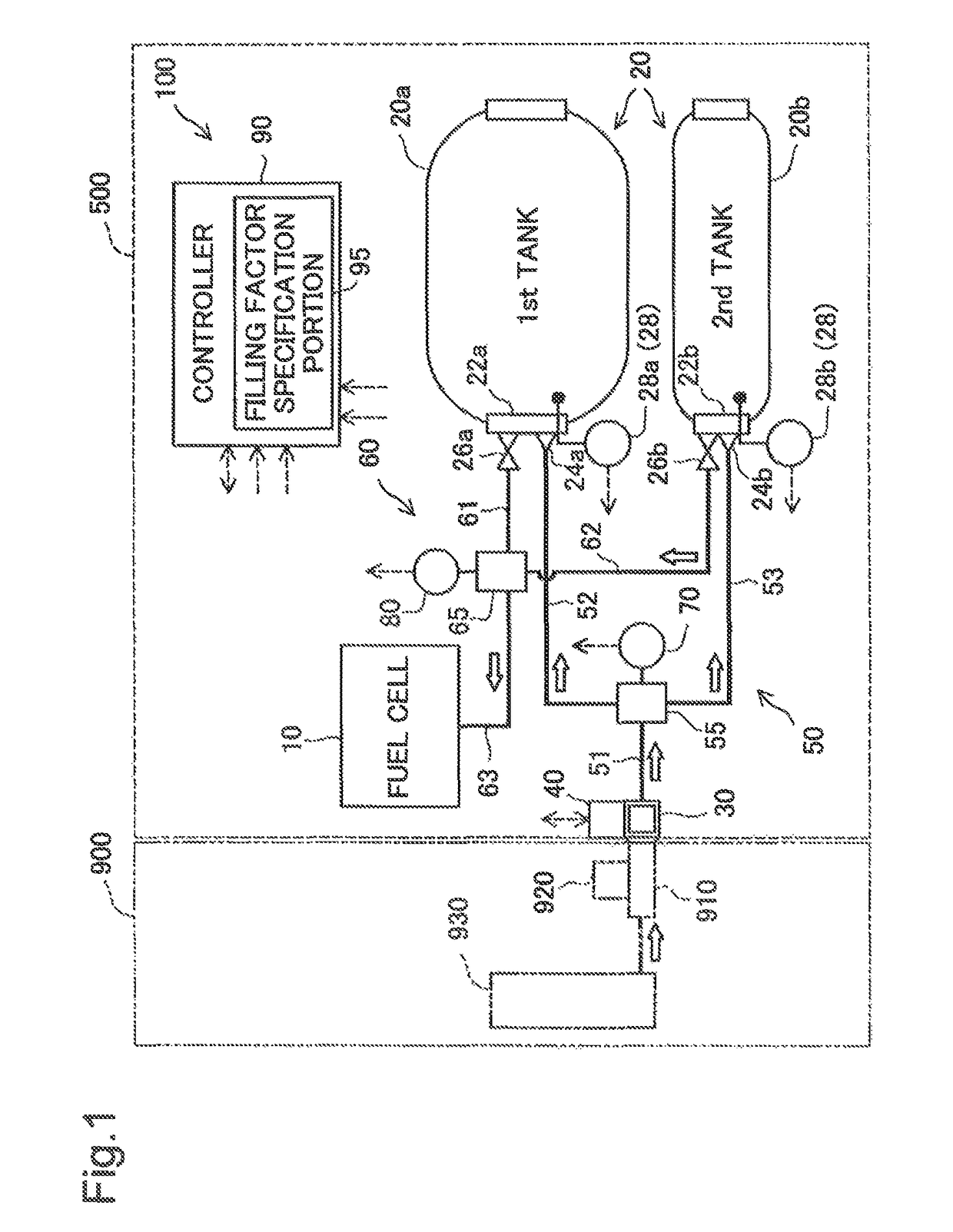
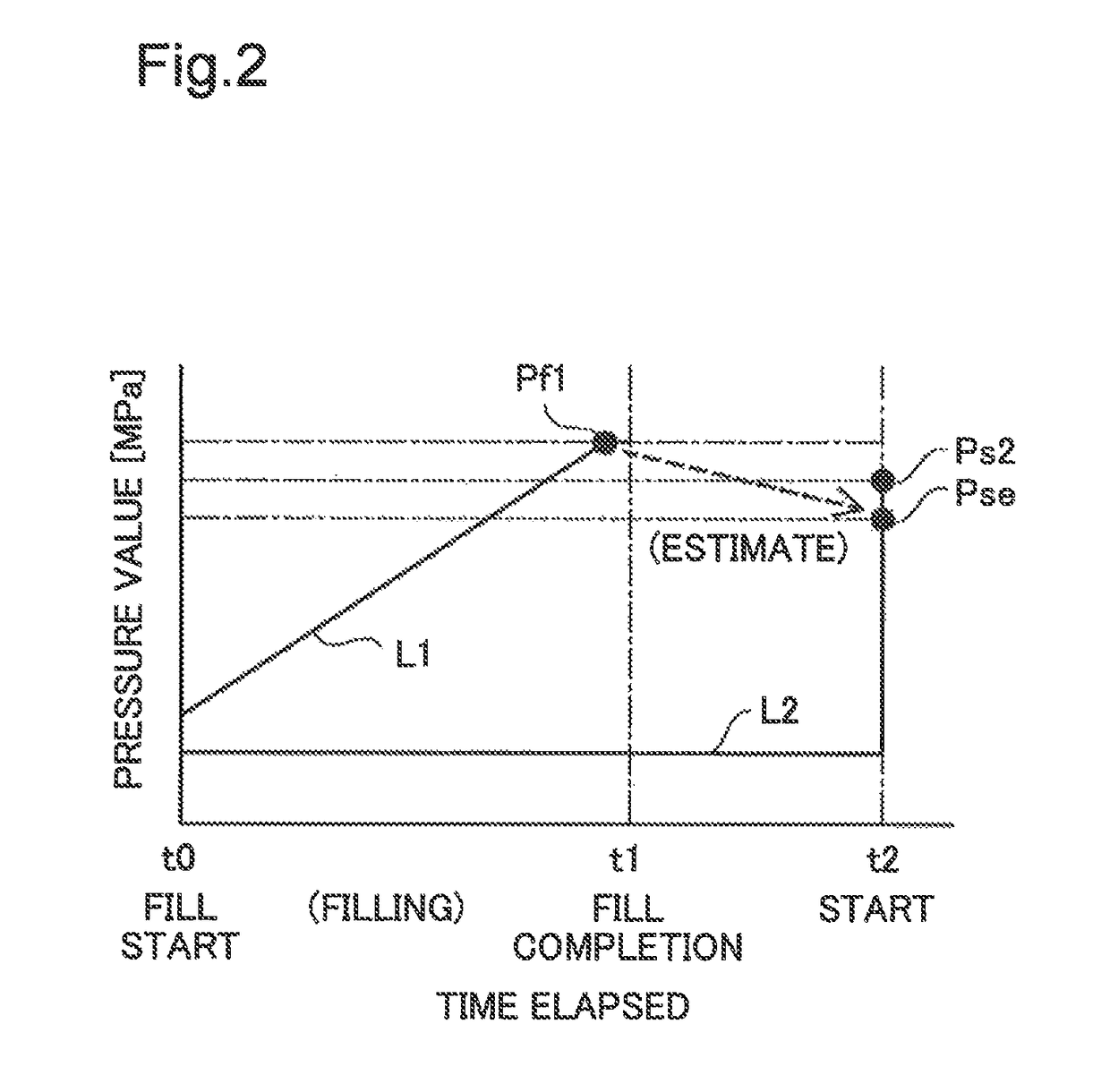
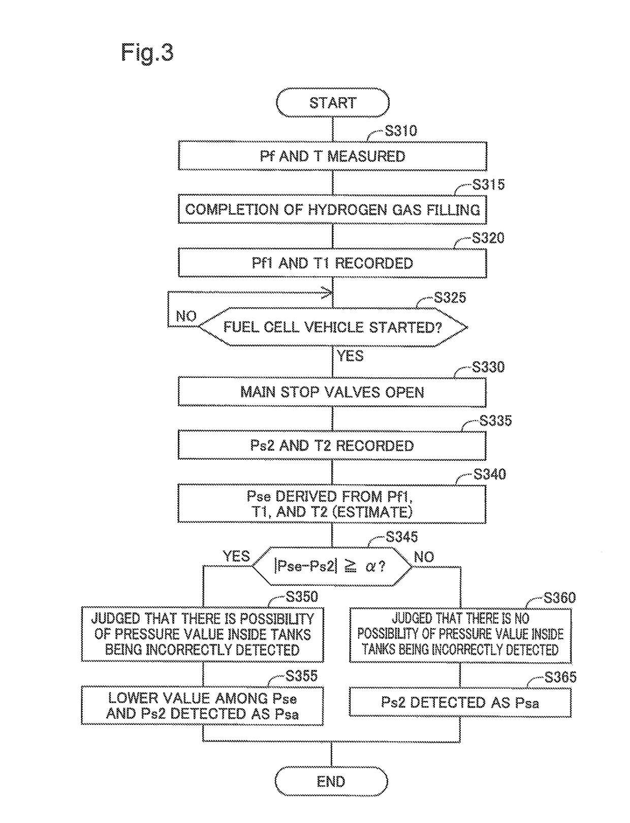
[0061]Although, in the above embodiment, the controller 90 records the maximum pressure value Pf1 that is the maximum pressure value among the fill-time pressure values Pf and uses it to estimate the estimated pressure value Pse, it may record the fill-time pressure value Pf at the time hydrogen gas filling is completed and use it to estimate the estimated pressure value Pse. This configuration makes it possible to derive the estimated pressure value Pse using a simple method. Additionally, although the controller 90 opens the main stop valves 26a and 26b when the fuel cell vehicle 500 (fuel cell system 100) is started, the main stop valves 26a and 26b may be opened without starting the fuel cell system 100. In this configuration, the opening of the main stop valves 26a and 26b may be used as a trigger to record the measured pressure value Ps2 and the temperature T2. Even in such a configuration, the same advantages are achieved as in the fuel cell system 100 of the above ...


PUM

PropertyMeasurementUnit
temperature Taaaaaaaaaaa
internal pressureaaaaaaaaaa
pressureaaaaaaaaaa

Abstract

A fuel cell system comprises a fuel cell, a tank, a 1st pressure sensor that measures a fill-time pressure, a 2nd pressure sensor that measures a supply piping pressure, a temperature sensor that measures an internal temperature of the tank; and a controller that, when the fuel cell starts, derives an estimated pressure value of the supply piping pressure based on a 1st pressure value that shows the fill-time pressure, the internal temperature when the 1st pressure value was measured, and the internal temperature when the supply piping pressure was measured, and that detects as the supply piping pressure the lower value among the estimated pressure value and the 2nd pressure value that shows the measured supply piping pressure.

Description

CROSS-REFERENCE TO RELATED APPLICATIONS[0001]The present application claims priority on the basis of Japanese patent application number 2014-226888 filed on Nov. 7, 2014, with the entirety of that disclosure incorporated into this application by way of reference.BACKGROUND[0002]Field[0003]The present invention relates to a fuel cell system.[0004]Related Art[0005]Conventionally, in fuel cell systems having a tank that stores fuel gas for supplying a fuel cell, the pressure value in the tank is detected. For instance, in the fuel cell system described in JP2002-089793A, a pressure sensor is disposed in piping that supplies hydrogen gas from a tank to a fuel cell, and the pressure value in the tank is detected using such a pressure sensor. Additionally, in this fuel cell system, the amount of hydrogen remaining in the tank is calculated based on the detected pressure value in the tank and the temperature in the tank. Generally, the amount of hydrogen remaining in the tank is expressed ...

Claims


Application Information

Patent Timeline
Patent Type & Authority Patents(United States)
IPC IPC(8): H01M8/04H01M8/0438H01M8/0432H01M8/04223H01M8/04225H01M8/04082
CPCH01M8/04223H01M8/04225H01M8/04373H01M8/04425H01M8/04388Y02T90/32H01M8/04201H01M2250/20H01M8/00H01M8/04H01M8/04298H01M8/04701H01M8/04708H01M8/04746H01M8/04753Y02E60/50Y02T90/40
Inventor KOMIYA, KENJIKONDO, MASAAKIYAMASHITA, AKIRA
Owner TOYOTA JIDOSHA KK
Why Eureka
Try Eureka