
Apparatus for driving a plurality of segments of LED-based lighting units
a technology of led-based lighting and apparatus, which is applied in the direction of lighting apparatus, electrical equipment, light sources, etc., can solve the problems of reducing efficiency, costing more, and difficult to miniaturize led-based lighting devices, and achieve the effect of efficient driving
- Summary
- Abstract
- Description
- Claims
- Application Information
AI Technical Summary
Benefits of technology
Problems solved by technology
Method used
Image

Examples
first embodiment
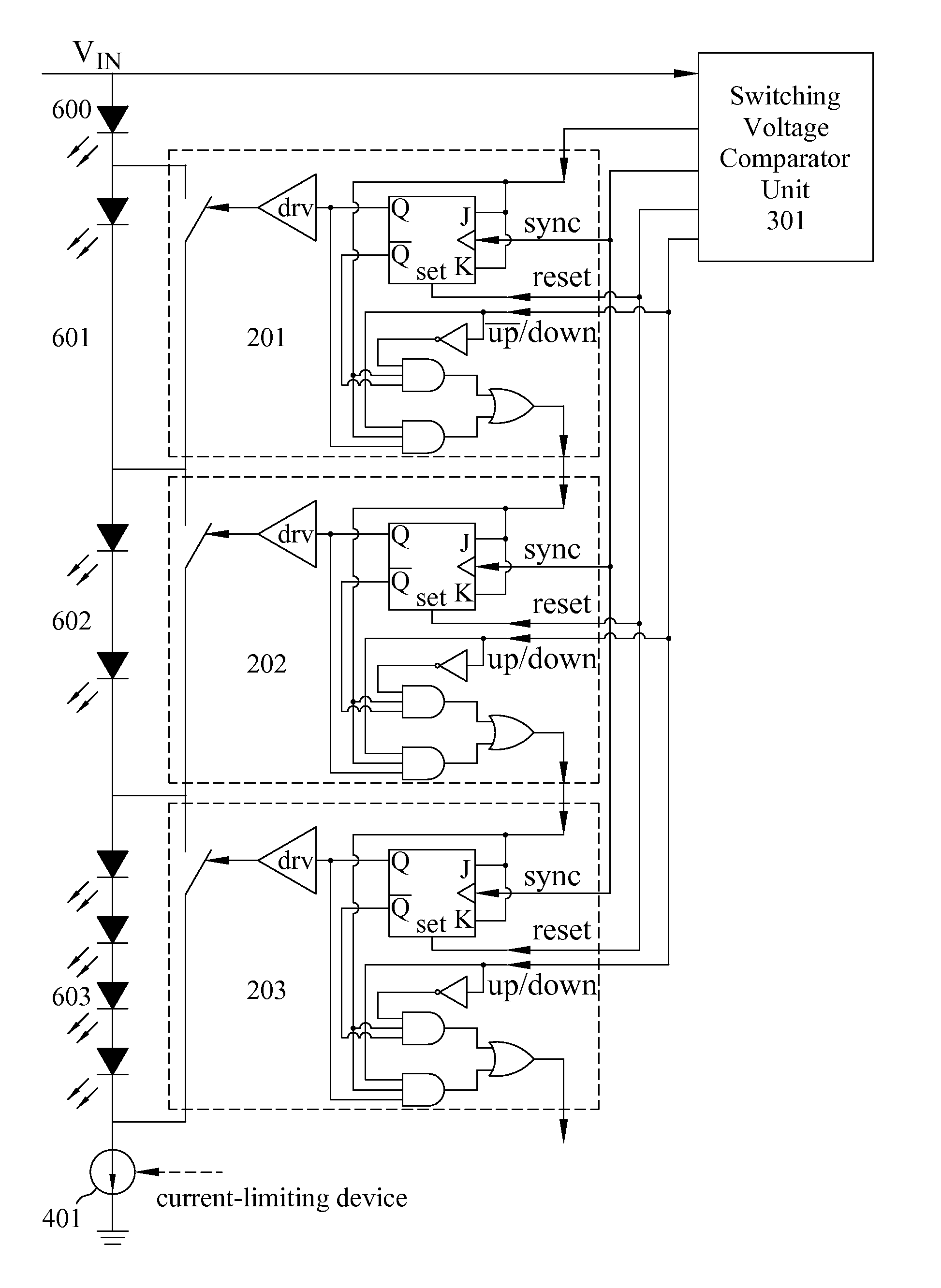
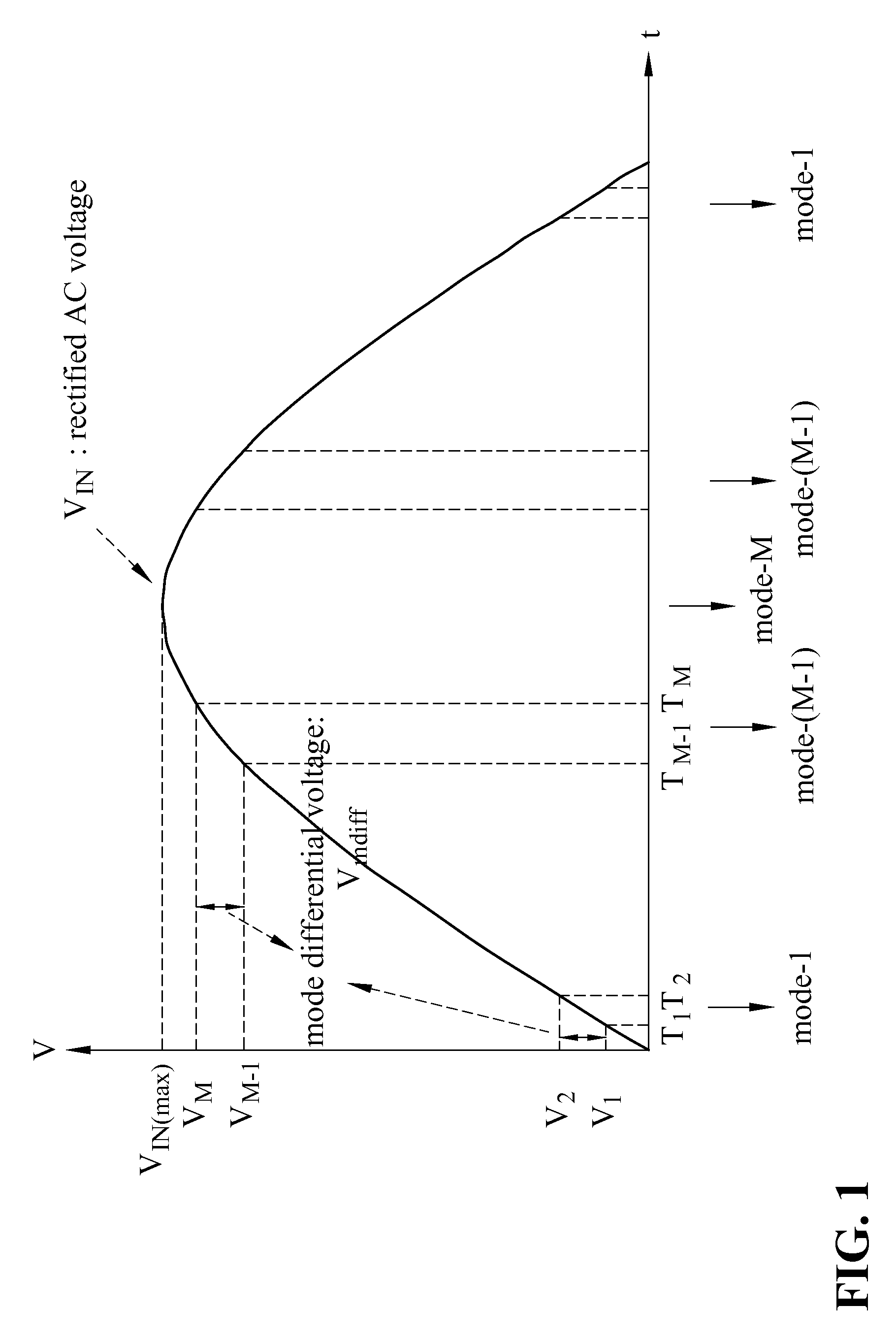
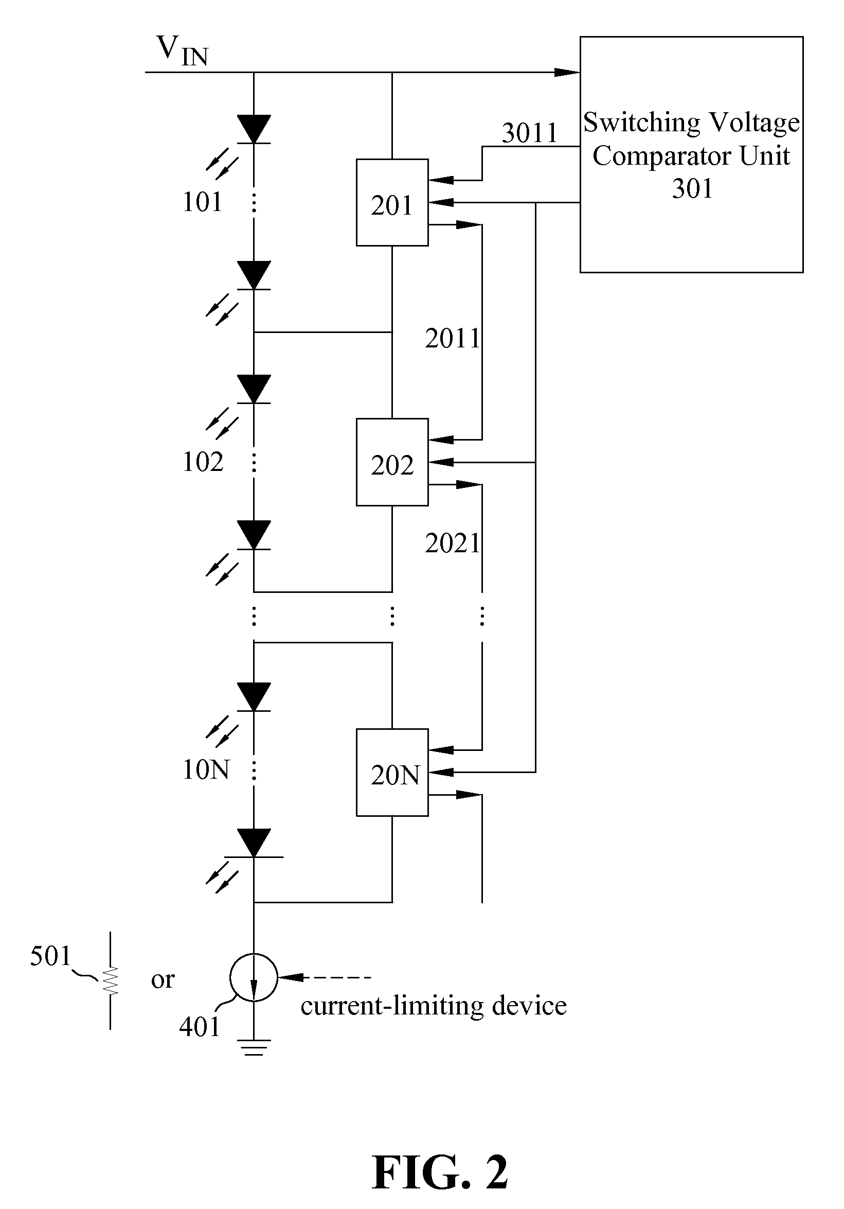
[0040]As shown in FIG. 1, the LED-based lighting apparatus of the present invention operates in Mode-i between time Ti and Ti+1 as the voltage level of the input voltage VIN increases between Vi and Vi+1. shown in FIG. 2, switch controllers 201, 202, . . . , 20N can be controlled by the switching voltage comparator unit 301 to selectively turn on the LED-based lighting units of one or more segments in LED-based lighting segments 101, 102, . . . , 10N.
[0041]As an example, during the period between time T1 and T2, switch controller 201 may be controlled by the switching voltage comparator unit 301 to turn on the LED-based lighting units in LED-based lighting segment 101 with all the other segments turned off, and switch controller 202 may be controlled to turn on the LED-based lighting segment 102 during the period between time T2 and T3 with all the other segments turned off. When the input voltage reaches the value between VM and VIN(Max), all the switch controllers 201, 202, . . ....
second embodiment
[0051]According to the present invention, each switch controller sends an output propagation signal to both its preceding and following switch controllers if they exist as shown in FIG. 7. Each switch controller also receives the output propagation signals sent from the preceding and following switch controllers if they are available. For example, switch controller 802 sends output propagation signal 8021 to both switch controller 801 and switch controller 803, and receives output propagation signal 8011 from switch controller 801 and output propagations signal 8031 from switch controller 803.
[0052]As can be seen in FIG. 7, the first switch controller 801 receives a first propagation signal 9011 from the switching voltage comparator unit 901 instead of a propagation signal from a preceding switch controller. In this embodiment, the last switch controller 80N receives a last propagation signal 9012 from the switching voltage comparator unit 901 instead of a propagation signal from a ...
PUM
 Abstract
Description
Claims
Application Information