Mini-rail external fixator

a fixator and minirail technology, applied in the field of external fixation systems and methods, can solve the problems of lack of flexibility, inability to adjust and/or pivot, and difficulty for physicians to achieve optimal clinical outcomes, and achieve the effect of greater flexibility in pin placemen

Active Publication Date: 2015-10-13
STRYKER EURO OPERATIONS HLDG LLC
View PDF98 Cites 5 Cited by
  • Summary
  • Abstract
  • Description
  • Claims
  • Application Information

AI Technical Summary

Problems solved by technology

Existing fixation systems on the market have many components thereof that are static and do not allow for certain adjustment and / or pivoting.
Lack of flexibility in a system may restrict attachment to certain bone areas at certain angles as well as restrict motion of the portion of the body that the external fixation system is being attached to in order to correct.
Because of such lack of flexibility, such systems may make it more difficult for the physician to achieve an optimal clinical outcome.
Existing mini-rail systems are generally bulky, unnecessarily complex in procedure, and utilize pin configurations that generally flex during correction of bone fragments.
In other prior art systems, the pin clamps may allow for some polyaxial rotation of the pins that are coupled thereto; however, other degrees of freedom are generally restricted between the pin clamp and the fixation rod that the pin clamp is coupled to.
Further, many systems are not configured such that other fixation devices could attach to it unless such other fixation devices are specifically designed to interface with the threaded rod or cage thereof, for example.

Method used


Image

  • Mini-rail external fixator
  • Mini-rail external fixator
  • Mini-rail external fixator

Examples


first embodiment

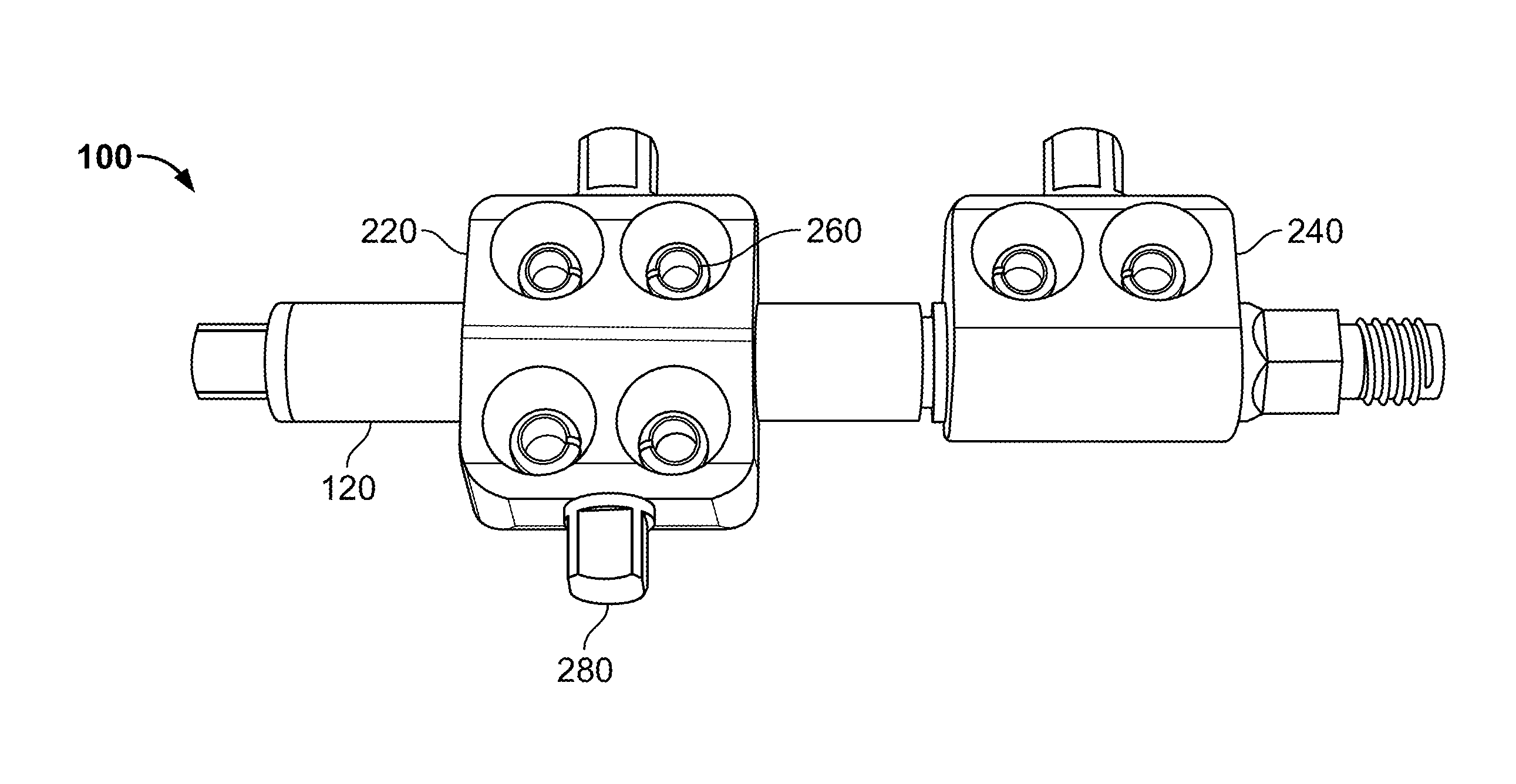
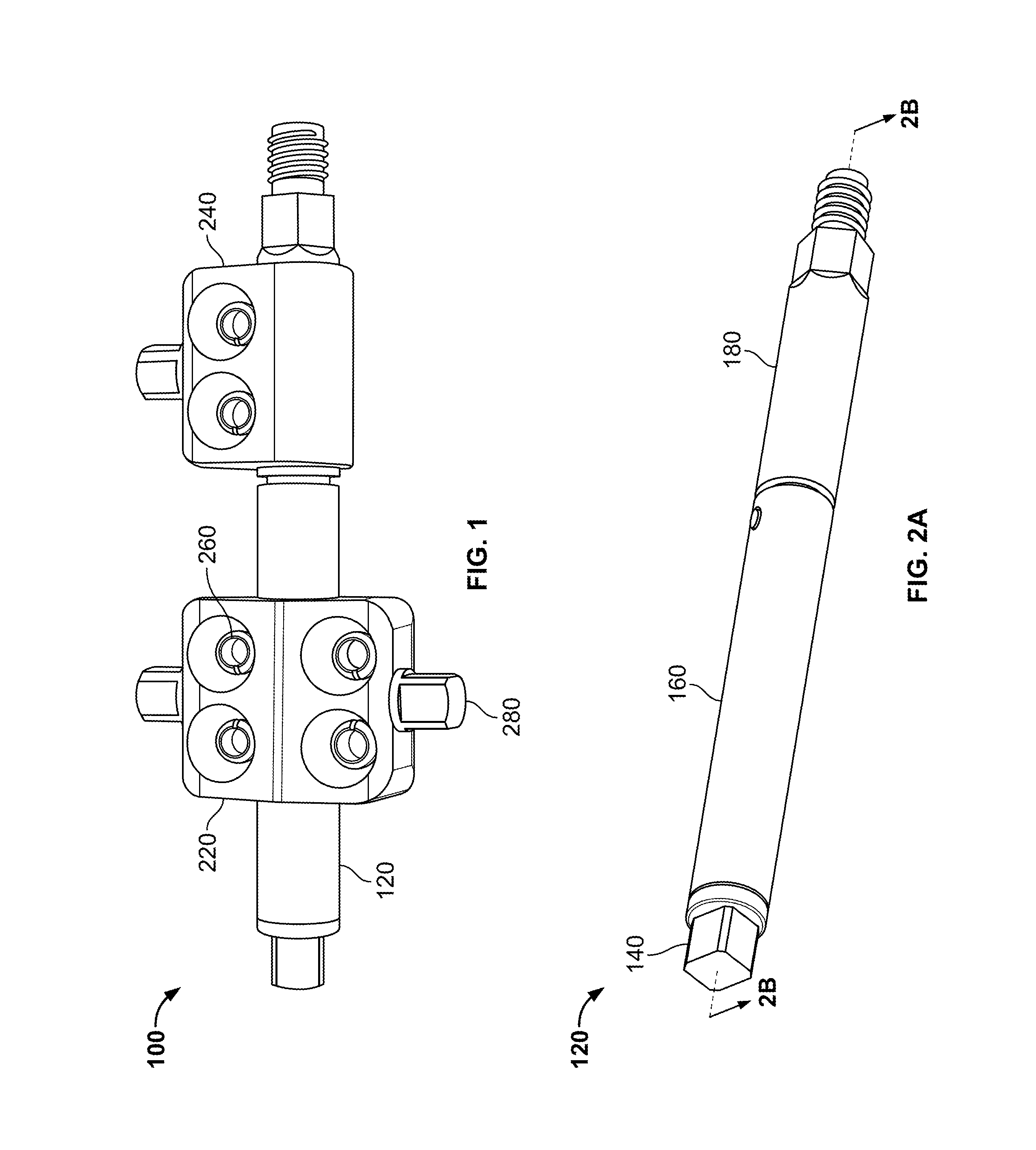
[0047]FIG. 3 is a perspective view of a housing 300 of the external fixation system 100. Housing 300 includes side surfaces 302, 304 having a bore 306 therethrough. Bore 306 defines a longitudinal axis L2 of housing 300. Housing 300 includes a front face 312 and a back face 314 and a plurality of apertures 322 therethrough. Each of the plurality of apertures 322 has a longitudinal axis that is perpendicular and offset to longitudinal axis L2 of housing 300. An internal circumference of each of the plurality of apertures 322 perpendicular to the longitudinal axes of each of the plurality of apertures 322 and is open to bore 306 such that a portion of each of plurality of apertures 322 intersects bore 306. Housing 300 further includes bores 332 extending into housing 300 from bottom and top surfaces 334, 336 thereof. Bores 332 are also open to bore 306 such that a portion of bores 332 intersect bore 306. In the embodiment shown, housing 300 includes four apertures 322. Two of the four...

second embodiment

[0048]FIG. 4A is a perspective view of a housing 400 of the external fixation system 100. Housing 400 includes side surfaces 402, 404 having a bore 406 therethrough. Bore 406 defines a longitudinal axis L3 of housing 400. Housing 400 includes a front face 412 and a back face 414 and a plurality of apertures 422 therethrough. Each of the plurality of apertures 422 has a longitudinal axis that is perpendicular and offset to longitudinal axis L3 of housing 400. An internal circumference of each of the plurality of apertures 422 perpendicular to the longitudinal axes of each of the plurality of apertures 422 and is open to bore 406 such that a portion of each of plurality of apertures 422 intersects bore 406. Housing 400 further includes bore 432 extending into housing 400 from a top surface 436 thereof. Bore 432 is also open to bore 406 such that a portion of bore 432 intersects bore 406. In the embodiment shown, housing 400 includes two apertures 422.

[0049]FIGS. 5-6 are views of one e...

third embodiment

[0059]FIG. 7 is a perspective view of a housing 700 of the present invention. Housing 700 includes a base member 720, first and second plate members 740, 760, a plurality of pin clamps 500, and first and second fixation post members 780. Base member 720 is coupled to a clamping mechanism that includes bottom and top plate members 740, 760, the plurality of pin clamps 500 and first and second fixation post members 780. Base member 720 has a bore 722 therethrough and a longitudinal axis L4. A longitudinal axis of first and second plate members 740, 760 is preferably parallel with longitudinal axis L4 of base member 720, but may be angled with respect to longitudinal axis L4 of base member 720.

[0060]First and second plate members 740, 760 each have a threaded vertical bore 790 extending through outwardly and inwardly facing surfaces 750, 770 thereof. First and second plate members 740, 760 further have a longitudinal recess 775 in the inwardly facing surfaces 770 thereof. Longitudinal ...


PUM


Abstract

Described herein are external fixation systems for correcting bone deformities in adjacent bones or fragments thereof. The systems herein include first and second elongate rods that translate with respect to one another via rotation of an actuation member at an end of one of the rods. At least one housing is coupled along a length of one of the rods. The at least one housing includes at least one pin clamping member for clamping an end of a fixation pin therein. When the at least one pin clamping member is in an unlocked state, the fixation pin can rotate in polyaxial directions. When in a locked state, the angle of fixation wire with respect to the rods is set. The locked and unlocked state of the at least one pin clamping member is determined by the positing of a fixation member with respect to the housing it is coupled to.

Description

FIELD OF THE INVENTION[0001]The present invention relates to external fixation systems and methods, and in particular relates to a telescoping body having coupled thereto a ball and socket type pin clamp that allows pin members to have independent trajectories when engaged to both the pin clamp of the external fixation system and a bone of a patient.BACKGROUND OF THE INVENTION[0002]Many different types of bone deformities can be corrected using external fixation systems. Such systems generally use rings, fixation plates, threaded rods or struts for manipulation, angulation, and translation of the deformities of bones.[0003]Existing fixation systems on the market have many components thereof that are static and do not allow for certain adjustment and / or pivoting. Lack of flexibility in a system may restrict attachment to certain bone areas at certain angles as well as restrict motion of the portion of the body that the external fixation system is being attached to in order to correct...

Claims


Application Information

Patent Timeline
Patent Type & Authority Patents(United States)
IPC IPC(8): A61B17/64A61B17/66
CPCA61B17/6466A61B17/66A61B17/6416A61B17/60A61B17/645
Inventor CHANG, ERIC
Owner STRYKER EURO OPERATIONS HLDG LLC
Why Eureka
Try Eureka