Electromagnetically actuated clutch

a technology of electromagnetic field and clutch, which is applied in the direction of magnetically actuated clutches, mechanical actuated clutches, and gearing, etc., to achieve the effect of reducing the strength of electromagnetic field produced by the coil, less copper, and reducing weigh

Active Publication Date: 2015-12-15
FORD GLOBAL TECH LLC
View PDF11 Cites 4 Cited by
  • Summary
  • Abstract
  • Description
  • Claims
  • Application Information

AI Technical Summary

Benefits of technology

[0009]Due to the mechanical advantage produced by use of the levers, the strength of the electromagnetic field produced by the coil is reduced in comparison to conventional applications, allowing use of a smaller coil, having less copper, lower weight, and a much smaller package size.

Problems solved by technology

The clutch member can be a friction plate or dog clutch, which does not allow any slipping between rotating components during engagement.

Method used


Image

  • Electromagnetically actuated clutch
  • Electromagnetically actuated clutch
  • Electromagnetically actuated clutch

Examples


Embodiment Construction

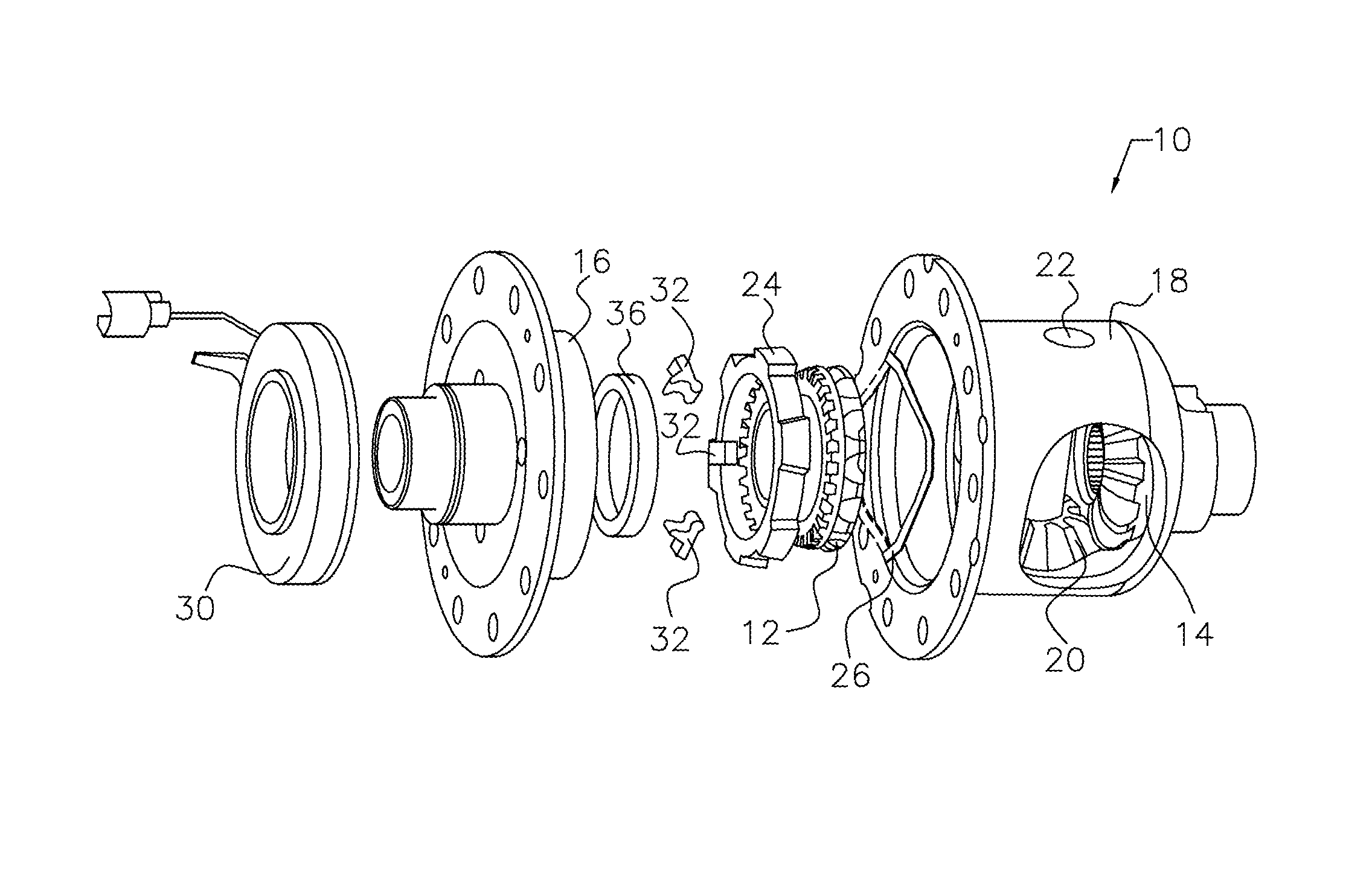
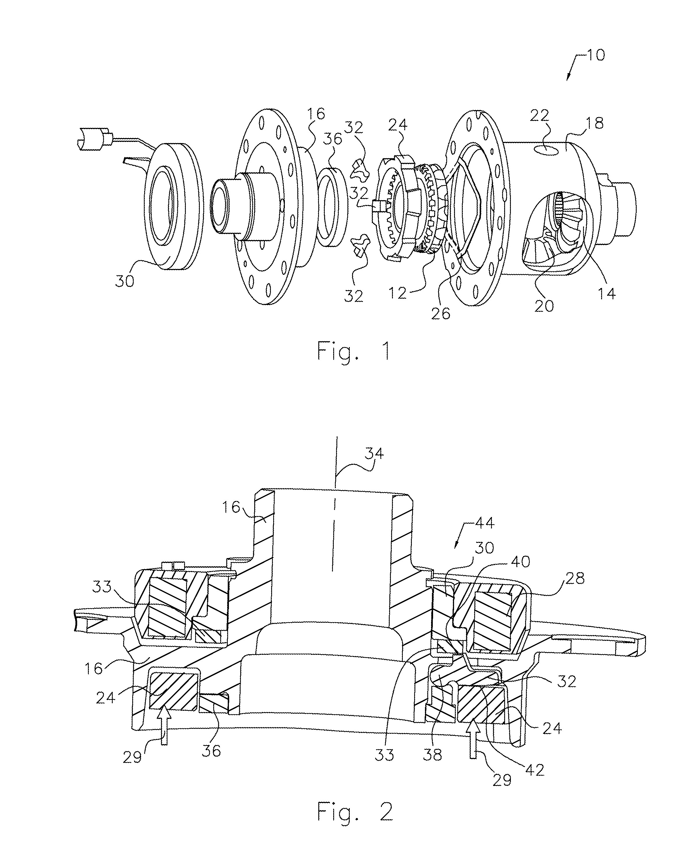
[0020]Referring now to the drawings, there is illustrated in FIG. 1 a rear axle locking differential mechanism 10, in which one or more of the side gears 12, 14 is selectively rotationally fixed to a differential case housing 16. The description refers to side gear 12 being secured against rotation to the left-hand case 16, but either side gear 12, 14 could be secured selectively to either the right-hand case 18 or the left-hand case 16. The gear teeth of the right-hand side gear 14 are engaged with the gear teeth of one of the bevel pinions 20. A pinion shaft 22, which extends through the walls of case 18, supports the bevel pinions 20 in rotation about the cylindrical surface of the pinion shaft 22.

[0021]A locking ring 24, rotationally fixed to case 16, can move axially within the differential case 16.

[0022]A return spring 26, located between the locking ring 24 and a spring seat in the right-hand case 18, provides an elastic force 29, which keeps the locking ring 24 disengaged fr...


PUM


Abstract

A clutch mechanism includes a coil of wire for producing an electromagnetic field, a locking ring secured against rotation within a case or housing, a gear engageable with the locking ring, and a lever that pivots in response to the electromagnetic field produced by energizing the coil causing the locking ring to engage the gear and hold the gear against rotation.

Description

BACKGROUND OF THE INVENTION[0001]1. Field of the Invention[0002]This invention relates generally to a dog clutch actuation mechanism, and more particularly to a locking differential mechanism for a motor vehicle axle.[0003]2. Description of the Prior Art[0004]Rotating components often require a clutch to transfer torque and rotation from one rotating component to another. The clutch member can be a friction plate or dog clutch, which does not allow any slipping between rotating components during engagement.[0005]Common automotive applications of torque transfer clutches include transmissions, transfer cases, air conditioner compressors, power take-offs and many others. Torque transfer clutches are also commonly used in non-automotive applications such as industrial motors, conveyors, agricultural equipment and lawn mowing equipment. The torque transfer clutches can be engaged via compressed air, hydraulic fluid, mechanical leverage or magnetic actuation.[0006]Many electronically-con...

Claims


Application Information

Patent Timeline
Patent Type & Authority Patents(United States)
IPC IPC(8): F16D27/118F16H48/34F16H48/08F16H48/24
CPCF16D27/118F16H48/08F16H48/24F16H48/34F16H2048/346
Inventor ANDONIAN, BRIAN J.GUO, JIHONGHINDI, YASSERISKEN, II, DENNIS W.POVIRK, JACOB M.
Owner FORD GLOBAL TECH LLC
Why Eureka
Try Eureka