Laser particle projection system

a projection system and laser technology, applied in the field of light projection systems, can solve problems such as the distortion of the image toward the outer edges of the screen

Active Publication Date: 2016-06-14
BLISSLIGHTS LLC
View PDF13 Cites 41 Cited by
  • Summary
  • Abstract
  • Description
  • Claims
  • Application Information

AI Technical Summary

Benefits of technology

[0024]In a particularly preferred embodiment, the first lens assembly is an F-theta lens. The F-theta lens design is optimized for a flat field in the image plane. In an F-theta lens, the output beam displacement is equal to f(θ), where θ is the angle of incidence of the input beam, measured along an axis through the lens. Thus, the input beam angular velocity is directly proportional to the output beam angular velocity. The use of such a lens also has another advantage, in that, as discussed below, it allows the unit to use smaller deflections of the beam directing mirrors to create the required deflection of the beam through the various lens elements of the system and then onto the movie screen.

Problems solved by technology

If the light beam is being projected against a flat screen or other surface, this can result in distortion of the image toward the outer edges of the screen.

Method used


Image

  • Laser particle projection system
  • Laser particle projection system
  • Laser particle projection system

Examples


Embodiment Construction

[0032]The present invention can be used in a variety of different indoor or outdoor entertainment venues or other venues where it is necessary or desirable to project a light beam against one or more surfaces.

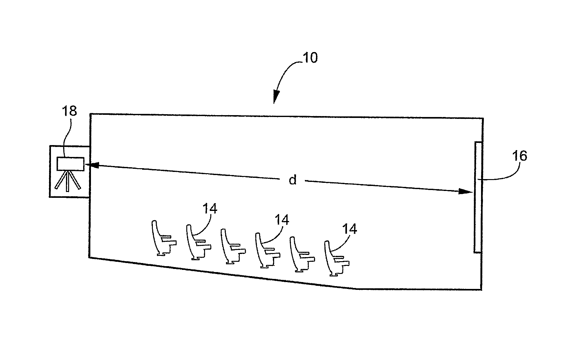
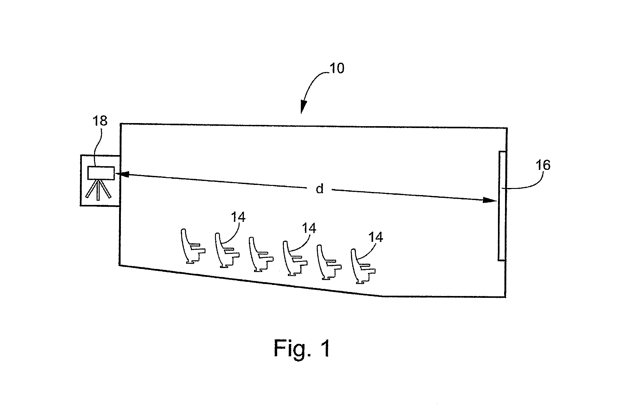
[0033]The system is described below in the context of an exemplary application in a typical movie theater 10, shown in FIG. 1. A movie or video projector (not shown) positioned in a projection room 12 at the back of the theater, viewed from the side in FIG. 1. A plurality of seats 14 provide seating for the members of the audience. A movie screen 16 is located at the other end of the theater 10.

[0034]A particle effect projector 18 in accordance with the present invention is positioned alongside the video projector. Alternatively, the particle effect projector 18 can be incorporated into the housing of the video projector. For ease of reference, the particle effect projector 18 is described herein as a stand-alone unit, although it will normally be connected to and synchronized ...


PUM


Abstract

An improved particle effect projector is disclosed that reduces the energy density of a laser beam projected through a movie theater or other entertainment venue, comprising an F-theta lens, a beam expander and a beam focuser with a long focal length that approximates the distance between the particle effect projector and the movie screen or other surface onto which the particle effect beam is being projected.

Description

CROSS-REFERENCE TO RELATED APPLICATIONS[0001]This application is a continuation-in-part of co-pending U.S. application Ser. No. 13 / 409,069, filed Feb. 29, 2012, which is hereby incorporated by reference in its entirety.BACKGROUND OF THE INVENTION[0002]The present invention pertains generally to the field of light projection systems, such as those used in movie theaters or other entertainment venues. More particularly, the present invention is directed to an apparatus for projecting a light, such as a laser light, onto a movie screen or other surface. The arrangement of lenses in the apparatus produces a beam that has a low energy density over most of the beam's distance, thereby reducing the risk of harm to a person sitting in the theater or venue.[0003]In recent years, laser particle effect systems have been developed that enable a laser light to be used to simulate the appearance of certain effects that are difficult to reproduce with conventional video techniques, or that otherwi...

Claims


Application Information

Patent Timeline
Patent Type & Authority Patents(United States)
IPC IPC(8): G02B27/20G02B26/12G02B13/00G02B27/18
CPCG02B13/0005G02B27/18G02B26/125G02B26/101G02B26/105G06T13/60G09G3/02G06T2210/56G09G2330/12H04N9/3129
Inventor JOHNSON, RANDY E.
Owner BLISSLIGHTS LLC
Why Eureka
Try Eureka