Miniaturized Optical Tweezer Array

a micro-lenses array and optical tweezers technology, applied in the field of particle manipulation, can solve the problems of difficult manufacturing of micro-lenses of good quality (diffraction limitation), and the inability to capture objects in 3d by only using a single micro-lense array

Active Publication Date: 2009-07-30
ECOLE POLYTECHNIQUE FEDERALE DE LAUSANNE (EPFL)
View PDF5 Cites 17 Cited by
  • Summary
  • Abstract
  • Description
  • Claims
  • Application Information

AI Technical Summary

Benefits of technology

[0013]The general objective of the present invention is to provide an improved method and an improved apparatus with respect to prior art methods and apparatuses.
[0014]The main aspect of the present invention is the generation of 3-dimensional optical trapping system (optical tweezers) by using refractive and reflective micro-optical elements. The invention is particularly beneficial for the use of optical trapping in combination with small integrated devices such as for example in bio-chip technologies.

Problems solved by technology

It is known by those skilled in the art that micro-lenses of good quality (diffraction limited) with numerical apertures higher than 0.8 are difficult to manufacture.
As a consequence it is not possible with only refractive (or diffractive) micro-optical elements to generate sufficiently high gradient forces to balance the scattering (axial) forces exerted on the trapped objects, thus real 3D trapping of objects is impossible by only using a single micro-lens array.

Method used


Image

  • Miniaturized Optical Tweezer Array
  • Miniaturized Optical Tweezer Array
  • Miniaturized Optical Tweezer Array

Examples


Embodiment Construction

[0016]The invention is discussed below in a more detailed way with examples illustrated by the following figures:

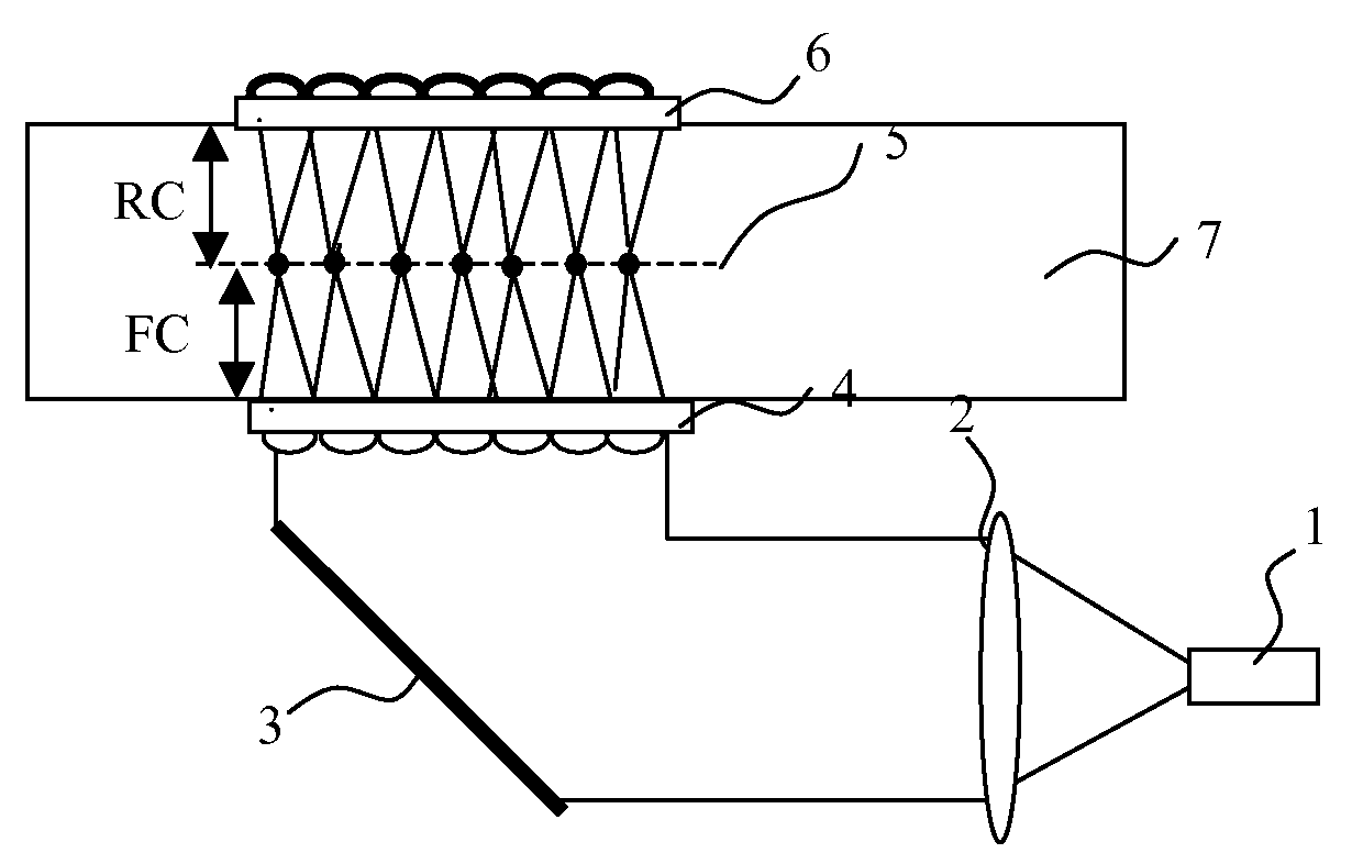
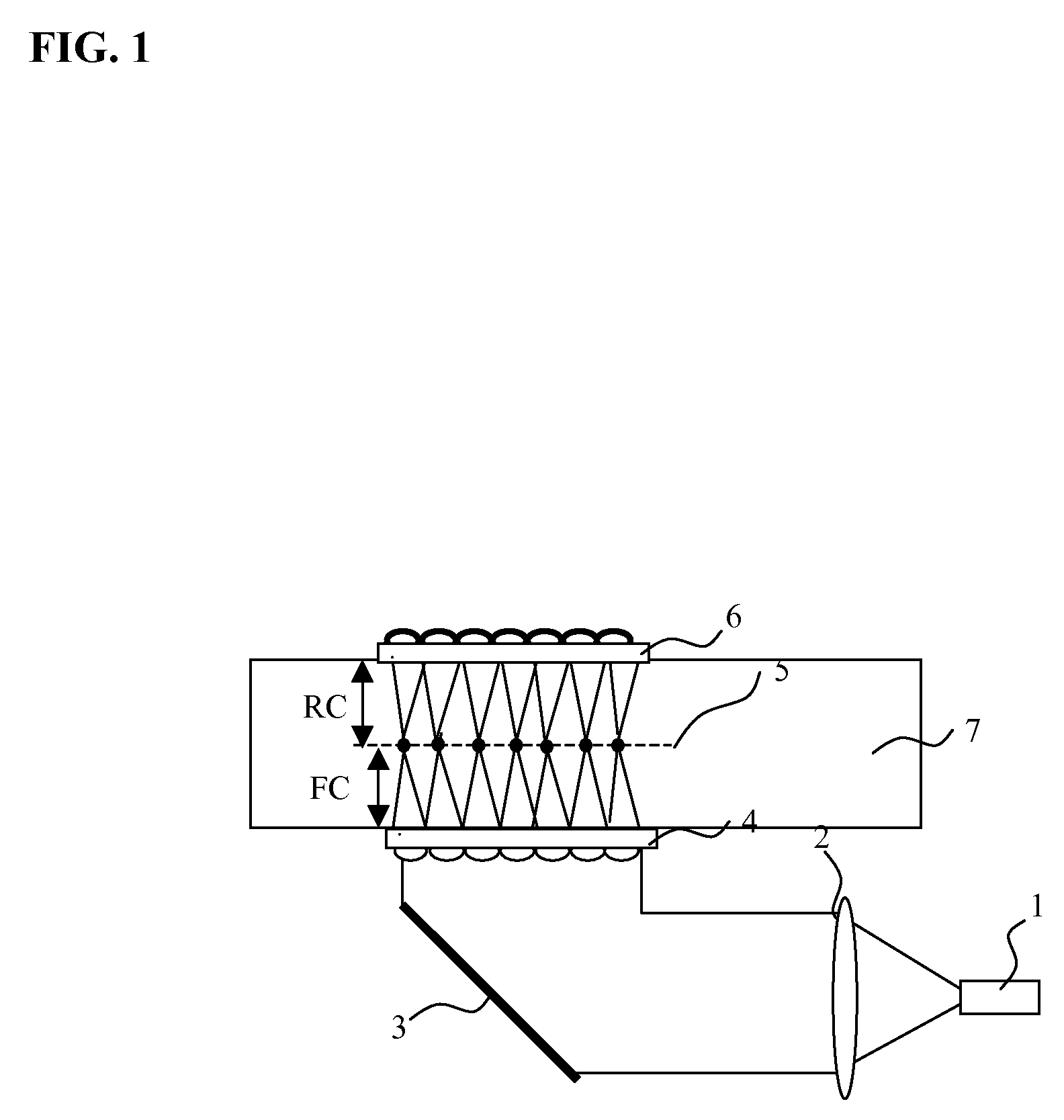
[0017]FIG. 1 represents a first embodiment of miniaturized trapping device according to the invention.

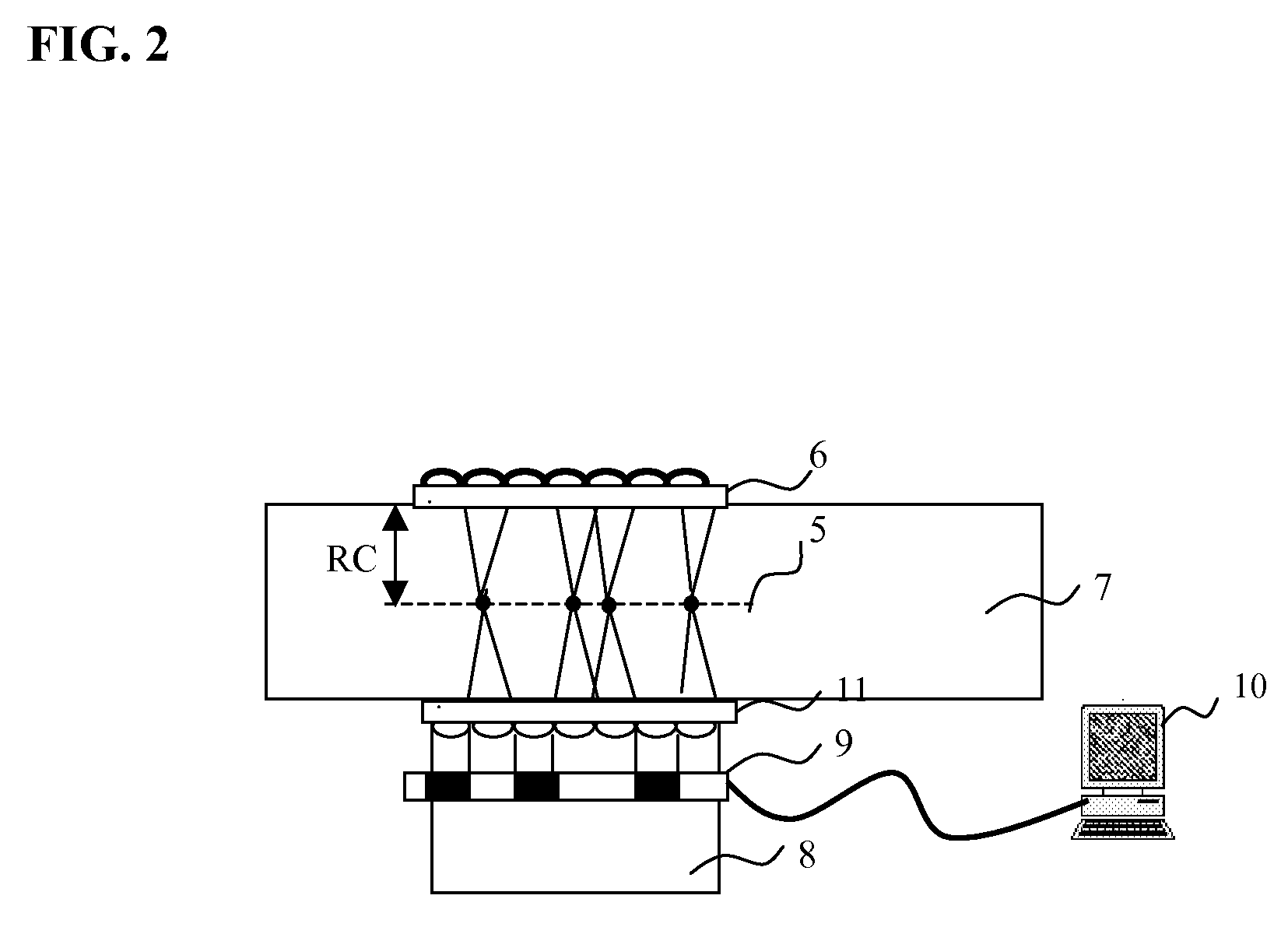
[0018]FIG. 2 represents another miniaturized trapping system according to the invention, this embodiment including optical valves.

[0019]FIG. 3 represents another miniaturized trapping system according to the invention, this embodiment being combined with a microscope objective.

[0020]FIG. 4 represents another miniaturized trapping system according to the invention, this embodiment being combined with a fluidic device.

[0021]FIG. 5 represents another trapping system according to the invention, this embodiment being combined with a fluorescence excitation and detection system for monitoring biochemical reaction

NUMERICAL REFERENCES USED IN THE FIGURES

[0022]1. Laser source[0023]2. Collimation Lens[0024]3. Relay mirror[0025]4. Micro-lens array[0026]5. Optical trapping plane[0027...


PUM


Abstract

Apparatus for forming a single or a plurality of threedimensional optical traps, the apparatus comprising: a. A collimated light source that is directed onto an array of focalizing refractive or diffractive elements providing a single or a plurality of focal areas, and b. An array of reflective elements, placed opposite to the said focalizing elements described in a), which reflect back the light into the said focal area. The invention also relates to a method for using this apparatus.

Description

FIELD OF INVENTION[0001]The present invention relates to the manipulation of particles by using electromagnetic radiation forces.[0002]It more precisely relates to optical tweezers and to a method for using such objects.STATE OF THE ART[0003]Momentum transfer between light and dielectric matter allows manipulation of micron-sized particles immersed in a fluid media whose refractive index is different than that of the particle. In particular, a highly focused laser beam allows three dimensional trapping of particles having an index of refraction higher than that of the surrounding media (A. Ashkin and J. M. Dziedzic, “optical trapping and manipulation of viruses and bacteria”, Science, 235, 1517 (1987)). It has already been demonstrated that optical trapping is a useful tool in biology and biophysics (K. C. Neuman and S. M. Block, “Optical trapping”, Rev. Sci. Instrum., 75, 2787 (2004)). Today there is a growing interest in lab-on-a-chip devices for biochemical applications, and opti...

Claims


Application Information

Patent Timeline
Patent Type & Authority Applications(United States)
IPC IPC(8): G02B27/42H01J40/14
CPCG02B21/32
Inventor BOER, GERBENMERENDA, FABRICEDELACRETAZ, GUYSALATHE, RENE
Owner ECOLE POLYTECHNIQUE FEDERALE DE LAUSANNE (EPFL)
Why Eureka
Try Eureka