Roll off hoist with hinged tail and hydraulic reeving system

a technology of hydraulic reeving system and roll-off hoist, which is applied in the direction of loading/unloading vehicle arrangment, transportation items, and refuse collection, etc., can solve the problems of insufficient durability and strength, system is not practical, and cannot be used indoors, so as to achieve the effect of more situations and small footprint during us

Active Publication Date: 2013-05-21
HEIL
View PDF39 Cites 18 Cited by
  • Summary
  • Abstract
  • Description
  • Claims
  • Application Information

AI Technical Summary

Benefits of technology

[0009]It is one object of the present invention to provide an improved system for loading and unloading containers regardless of the clearance height. It is another object of the present invention to provide an improved system for loading and unloading containers which is faster than conventional tilt frame systems and which has a smaller footprint during use which allows it to be used in more situations.
[0010]One preferred embodiment of the invention includes an elongated body (a / k / a “tilt frame”) that is attached to the wheeled vehicle's frame. The elongated body has a dual hydraulic cylinder reeving system and a hinged tail member. A pulley member is positioned at the pivot axis for the hinged tail member in order to allow the cable to more easily load and unload containers onto and off the tilt frame member.
[0011]The elongated body (or tilt frame) is pivotally connected to the vehicle chassis or frame near the rear end of the frame. One or more hydraulic cylinders are pivotally attached to a support member located near the front portion of the vehicle frame and to the elongated body near the front end, such that when the cylinder is fully retracted the elongated body is in a horizontal position parallel to and adjacent to the vehicle frame. When this cylinder begins to extend, the front end of the elongated body moves (tilts) upward in an arcuate path while the distal rear end of the body moves downward. The pivot point of the elongated body is typically the connection between the vehicle frame and the elongated body and is typically located near the rear of the body member. Raising the front end of the body while lowering the rear end facilitates loading and unloading of the containers. The tilt frame may also contain a number of rollers or other friction reducing surfaces positioned along its length which also makes loading and unloading easier by reducing the friction between the container bottom and the tilt frame.
[0013]During the loading and unloading of containers, the hinged tail member on the elongated body (tilt frame) is rotated and pivoted independently. One or more hydraulic cylinders are provided to rotate the hinged end (a k / a “tail portion”). With this embodiment, it is not necessary to tilt the elongated body to the same extent, or the conventional amount. Instead, the hinging of the tail portion can position the distal end of the elongated body adjacent the ground or other surface and allow the container to be loaded onto, or unloaded from, the elongated body and vehicle. The hinged tail member is preferably designed to have the same load strength of the tilt frame member. In addition, the hinged tail member has comparable lifting strength to the tilt frame which is independent of the reeving during loading.
[0014]The hinged tail member can be wider than the tilt frame member, and the hinged tail member could share a common pivot with the hinged tilt frame. In addition, for some types of containers, the hinged tail can be lowered for pick up and delivery of the containers without the necessity of lifting or tilting the tilt frame.

Problems solved by technology

These systems, although useful, have durability and strength problems.
One problem with existing tilt frame vehicle systems is that the tilt frame on the vehicle typically must be raised to a significant height for the loading and unloading of the containers and thus these systems have difficulty being used indoors or in situations where the ceiling height is low.
The vehicles with extendable end portions may be used in such circumstances, but are not sufficiently durable and require more floor space for loading and unloading.

Method used


Image

  • Roll off hoist with hinged tail and hydraulic reeving system
  • Roll off hoist with hinged tail and hydraulic reeving system
  • Roll off hoist with hinged tail and hydraulic reeving system

Examples


Embodiment Construction

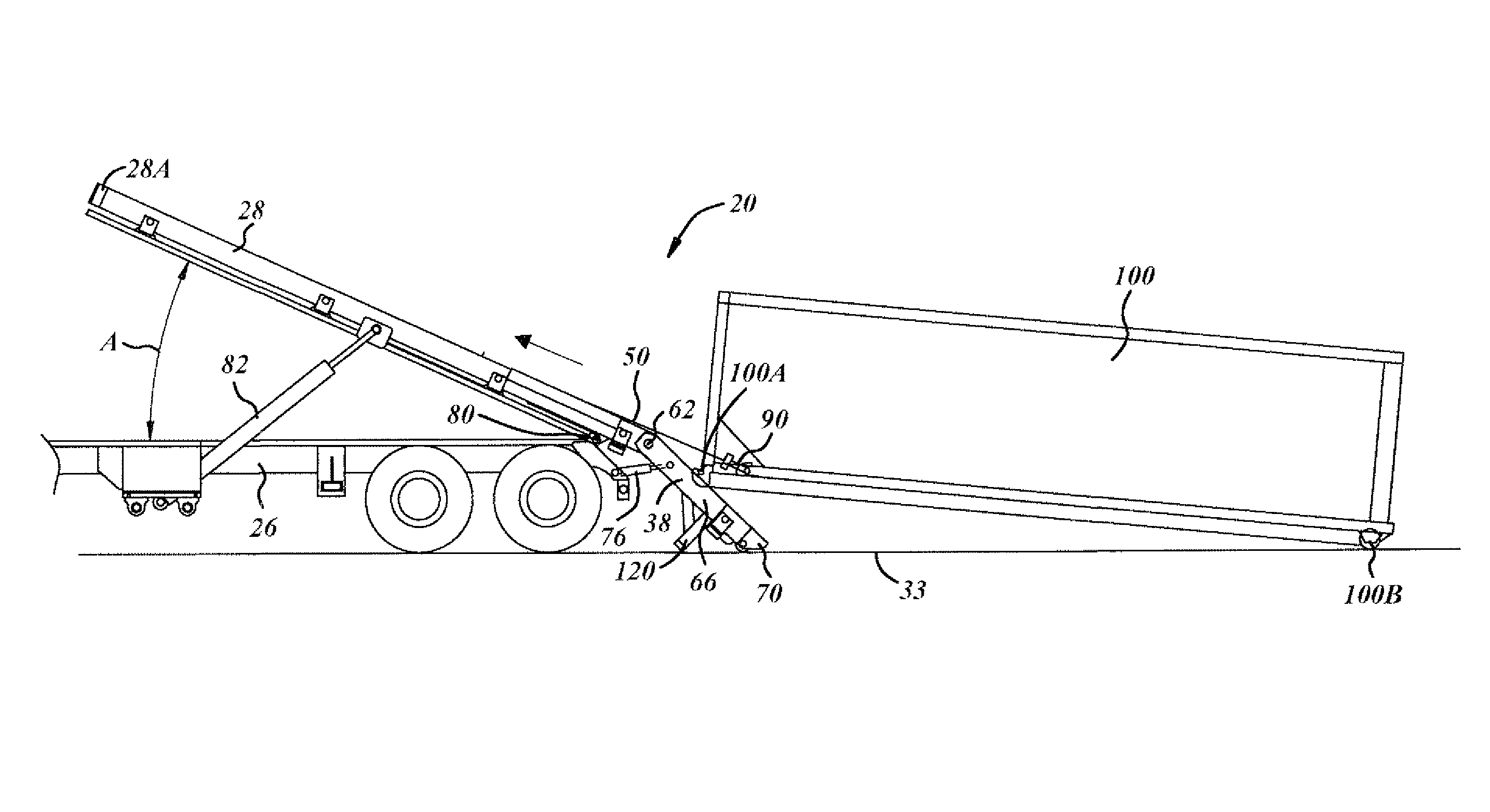
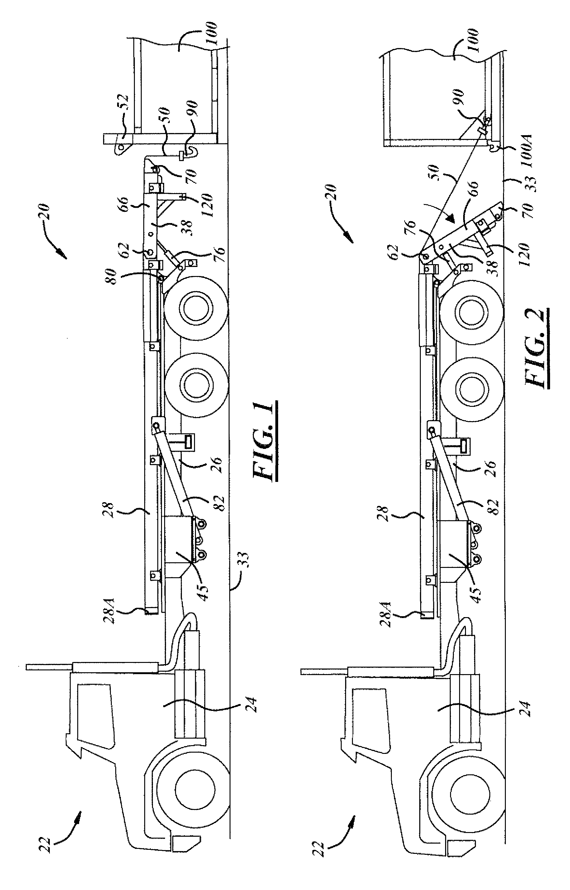
[0028]A preferred embodiment of the present invention is shown in FIG. 1 and referred to generally by the reference numeral 20. The system 20 is adapted to be mounted on a vehicle 22 which typically consists of a cab portion 24 and a chassis or vehicle frame 26. The invention includes an elongated body 28, also known as a “tilt frame,” which is adapted to be mounted on the frame 26 of the vehicle 22.

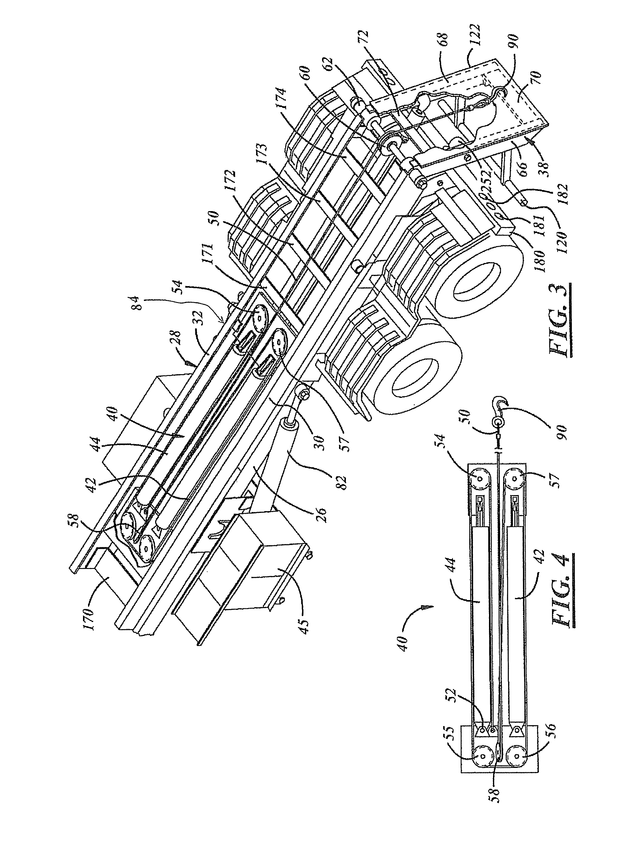
[0029]As shown in FIG. 3, the tilt frame 28 includes a pair of side rails 30 and 32, a dual hydraulic cylinder reeving arrangement 40, and a hinged tail or end member 38. In this regard, the use of the term “container” is not meant to be limiting. Although it is anticipated that the invention will be used primarily on refuse containers, it can be used to load or unload virtually any structure or object known today, including storage containers and the like.

[0030]A pulley or sheave 60 is positioned on the tilt frame where the hinged tail member rotates to accommodate the cable movement. T...


PUM


Abstract

A container handling system and method for a wheeled transport vehicle is disclosed that is capable of loading and unloading containers, particularly in locations where the overhead height is limited. A hinged tail member at the rear end of the elongated body (a / k / a tilt frame member) is rotated adjacent the ground allowing the containers to be loaded and unloaded without rotating the tilt frame to its maximum height. A cable reeving arrangement, such as a dual reeving arrangement, can be utilized to load and unload the containers.

Description

FIELD OF THE INVENTION[0001]This invention relates to a container handling system for a vehicle, more specifically it relates to a system and method for loading and unloading containers on and off wheeled vehicles.BACKGROUND OF THE INVENTION[0002]The art typically refers to systems for loading and unloading containers as “hook lift” systems and “cable hoist” systems. These systems have been extensively employed for the transport of various materials in the containers and have a pivotal tilt frame attached to the vehicle. In the usual case, containers are loaded or unloaded upon the bed of the truck or vehicle utilizing the hook lift system or the cable hoist system. One typical use for such systems is in the picking up and hauling of refuse. An open top or closed top container is typically delivered to, or picked up from, a point of use with either of these systems.[0003]Cable hoist systems typically use a cable reeving system like, for example, the one shown in U.S. Pat. No. 5,460,...

Claims


Application Information

Patent Timeline
Patent Type & Authority Patents(United States)
IPC IPC(8): B60P1/22
CPCB60P1/6454
Inventor DUELL, CHARLES A.WILLIAMS, RICHARD T.
Owner HEIL
Why Eureka
Try Eureka