Resuming a dynamic light effect in dependence on an effect type and/or user preference

Active Publication Date: 2021-10-05
SIGNIFY HLDG BV
View PDF11 Cites 0 Cited by
  • Summary
  • Abstract
  • Description
  • Claims
  • Application Information

AI Technical Summary

Benefits of technology

[0009]It is a first object of the invention to provide a method, which allows resumption of paused dynamic light scenes with behavior that is suitable for many situations.
[0010]It is a second object of the invention to provide an electronic device, which is able to resume paused dynamic light scenes with behavior that is suitable for many situations.
[0012]The inventors have recognized that a user desires different resumption behavior depending on the situation, and in particular depending on a type of the dynamic light effect and / or a user preference indicated for the dynamic light effect. The inventors have recognized that by resuming the dynamic light effect in a manner which depends on a type of the dynamic light effect and / or a user preference indicated for the dynamic light effect, the resumption behavior can be adapted to the situation at hand.
[0017]It may also be beneficial to control the one or more light sources to resume the dynamic light effect at a speed which is faster than normal if the dynamic light effect is driven by an external source based on data other than content, e.g. sensor data. This allows the user to quickly preview what was missed and then catch up with the real-time data. For example, if the external source is a temperature sensor, the dynamic light effect might be paused for 10 minutes and upon resuming, the part of the dynamic light effect that would have been rendered in these 10 minutes might be rendered within one minute.
[0020]Said at least one processor may be configured to determine said speed such that said dynamic light effect will finish at the same time it would have finished if said dynamic light effect had not been paused. This reduces the risk of light effects being requested to be rendered simultaneously. Alternatively, the at least one processor may be configured to determine the speed based on how quickly the system needs to catch up with real-time data. In this case, the speed would typically depend on the time the dynamic light effect has been paused plus the time allocated to catching up with the real-time data.
[0022]Said at least one processor may be configured to control said one or more light sources to render one or more static light effects while said dynamic light effect is paused. This allows suitable lighting to be rendered while the dynamic light effect is paused.

Problems solved by technology

However, resuming from the point of pausing is frequently not the behavior that the user desires.

Method used


Image

  • Resuming a dynamic light effect in dependence on an effect type and/or user preference
  • Resuming a dynamic light effect in dependence on an effect type and/or user preference
  • Resuming a dynamic light effect in dependence on an effect type and/or user preference

Examples


Embodiment Construction

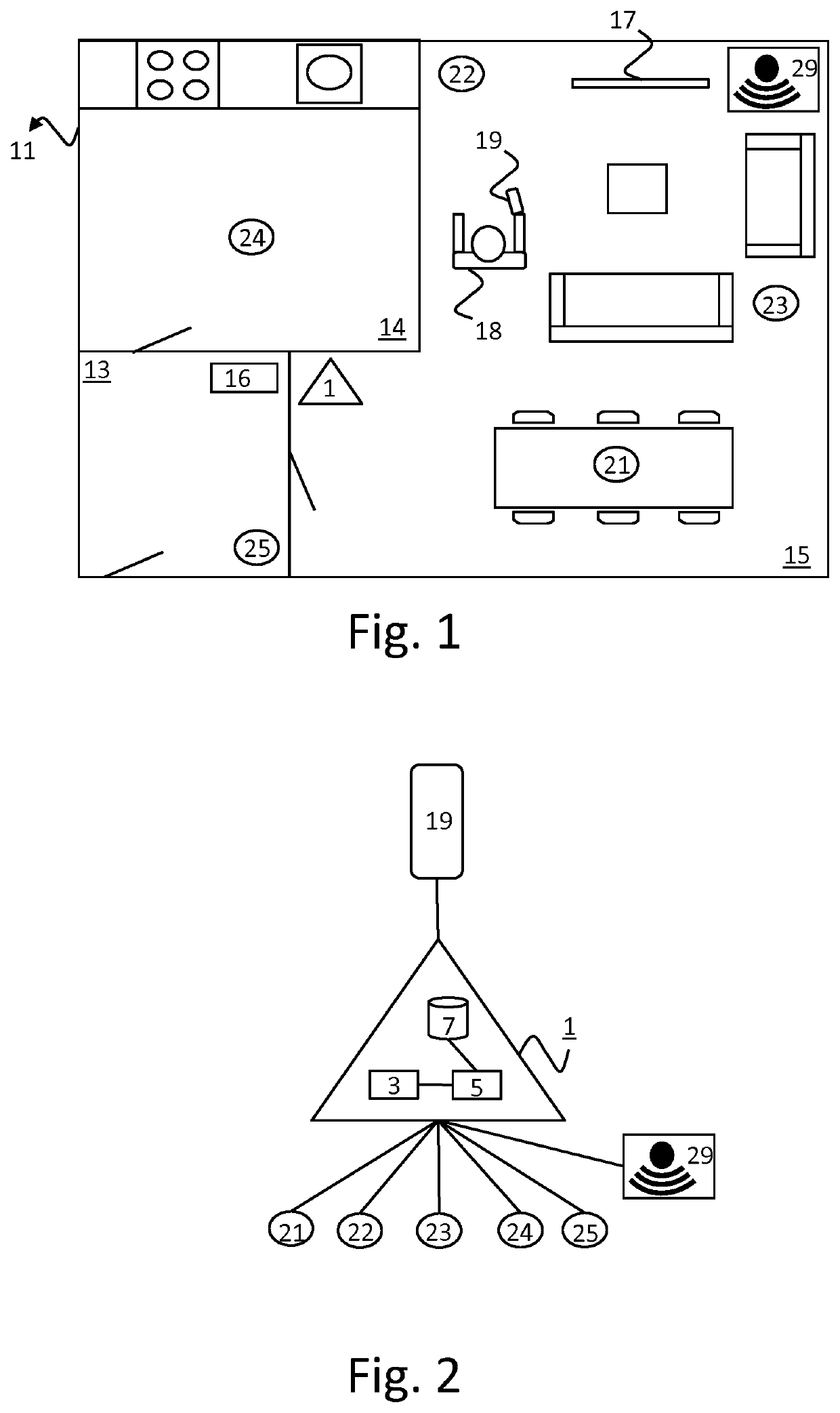
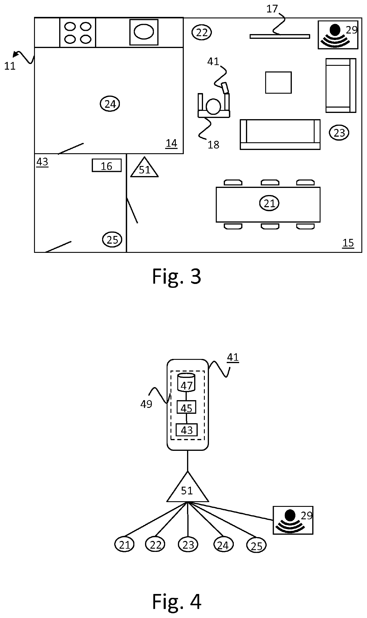
[0045]FIG. 1 depicts a floor 11 of a home that consist of a hall 13, a kitchen 14 and a living room 15. Five lights have been installed on floor 11: a light 24 in the kitchen 14, a light 25 in the hall 13, and lights 21-23 in the living room 15. Light 21 has been installed above a dinner table, light 22 has been installed to the left of a Television 17, and light 23 has been installed next to two couches. Furthermore, a motion detector 29 has been installed to the right of the Television 17. The lights 21-25 and the motion detector 29 are connected wirelessly to a bridge 1, e.g. via ZigBee or a protocol based on ZigBee. The bridge 1 is connected to a wireless access point 16, via a wire or wireless.

[0046]In the example depicted in FIG. 1, a person 18 is present on floor 11 and is using a mobile phone 19. The person 18 is also referred to as user 18. The mobile phone 19 is also connected (wirelessly) to the wireless access point 16. The mobile phone 19 may further be connected to a b...


PUM


Abstract

An electronic device is configured to control one or more light sources, to render a dynamic light effect, control the one or more light sources to pause the dynamic light effect at a first moment (72), and control the one or more light sources to resume the dynamic light effect at a second moment (73) in a manner (63-66) which depends on a type of the dynamic light effect and / or a user preference indicated for the dynamic light effect.

Description

CROSS-REFERENCE TO PRIOR APPLICATIONS[0001]This application is the U.S. National Phase application under 35 U.S.C. § 371 of International Application No. PCT / EP2019 / 053720, filed on Feb. 14, 2019, which claims the benefit of European Patent Application No. 18158608.2, filed on Feb. 26, 2018. These applications are hereby incorporated by reference herein.FIELD OF THE INVENTION[0002]The invention relates to an electronic device for controlling one or more light sources.[0003]The invention further relates to a method of controlling one or more light sources.[0004]The invention also relates to a computer program product enabling a computer system to perform such a method.BACKGROUND OF THE INVENTION[0005]The versatility of connected lighting systems keeps growing, offering more and more features to their users. These new features include new sensors, new types of user control, smart automated behavior, new forms of light usage (e.g. entertainment), amongst others. Lighting systems are al...

Claims


Application Information

Patent Timeline
Patent Type & Authority Patents(United States)
IPC IPC(8): H05B47/155H05B47/105H05B47/19H05B47/115
CPCH05B47/105H05B47/115H05B47/155H05B47/19Y02B20/40
Inventor ALIAKSEYEU, DZMITRY VIKTOROVICHSMITH, PIETER
Owner SIGNIFY HLDG BV
Why Eureka
Try Eureka