Method for monitoring a drive-by-wire system of a motor vehicle

a drive-by-wire system and motor vehicle technology, applied in the direction of testing/monitoring control systems, process and machine control, instruments, etc., can solve the problems of complex physical model having many variables, inability to intuitively understand the character of torque-based monitoring, and inability to adapt to the speed-based structure. , to achieve the effect of easy replacement, easy parameterization, and convenient adjustmen

Active Publication Date: 2018-01-11
ROBERT BOSCH GMBH
View PDF1 Cites 14 Cited by
  • Summary
  • Abstract
  • Description
  • Claims
  • Application Information

AI Technical Summary

Benefits of technology

[0027]According to a further specific embodiment, for the monitoring of the monitored quantity a model is used for the motor vehicle operation. For example, for various driving situations, such as acceleration or deceleration, various simple models can be provided. In this sense, no coupling takes place between the functional level (level 1) and the monitoring level (level 2) using characteristic maps that are expensive to populate with data. Because the models of the monitoring level contain different variables than in the functional level, they are largely decoupled from the functional level. These models can easily be adapted, are easy to parameterize, and can easily be replaced, because of the modular design.
[0028]For example, the models have a polynomial function, a spline function, an exponential saturation curve, an exponential decay function, and / or a random walk function that links the at least one input value with the target value. In this way, the models make use of standard functions, so that the models have a particularly simple design and use a particularly small amount of computing resources.

Problems solved by technology

A torque-based structure of the monitoring however does not have an intuitively understandable character, because the driver of the motor vehicle does not consciously control the torque.
In addition, a complex physical model having many variables is required.
In addition, in contrast to a torque-based structure an acceleration-based structure of the monitoring level contains different variables than does the functional level, because for example an activation of auxiliary components of the motor vehicle is not relevant for this type of monitoring.
However, the acceleration-based structure also does not always have an intuitively understandable character.
In addition, the monitoring level requires a complex physical model that is permanently calculated and therefore consumes computing resources of a microcontroller.
In addition, the change of the input quantity over time permits acquisition of an error in a particularly intuitive manner, e.g., if a driver of the motor vehicle relieves force on the gas pedal of the motor vehicle, i.e., lets up on the gas, but at the same time the engine torque of the drive of the motor vehicle increases.
If, however, due to an error of the drive-by-wire system the gradient of the engine torque is increasing or is constant, this can easily be acquired by comparing the two gradients, and the error signal can thereupon be produced.
If, in contrast, the actual development over time of the monitored quantity ‘speed’ is now positive, an error is recognized.

Method used


Image

  • Method for monitoring a drive-by-wire system of a motor vehicle
  • Method for monitoring a drive-by-wire system of a motor vehicle
  • Method for monitoring a drive-by-wire system of a motor vehicle

Examples


Embodiment Construction

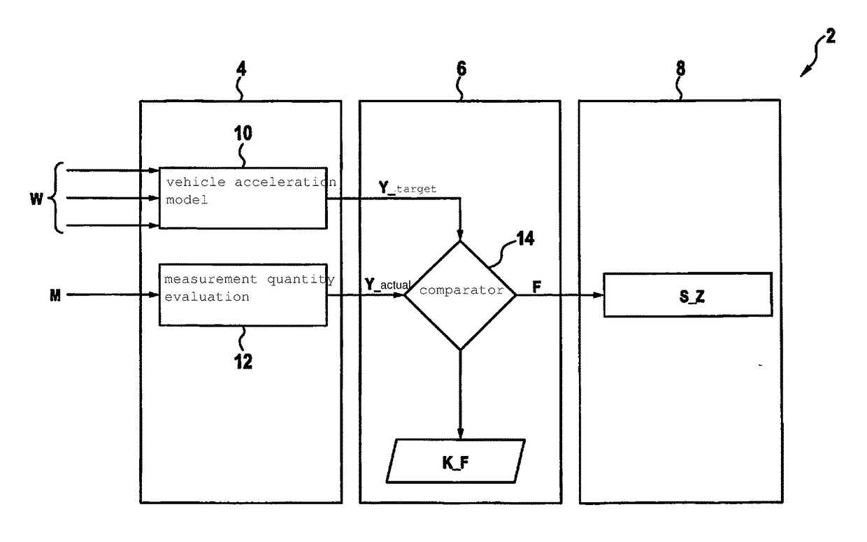
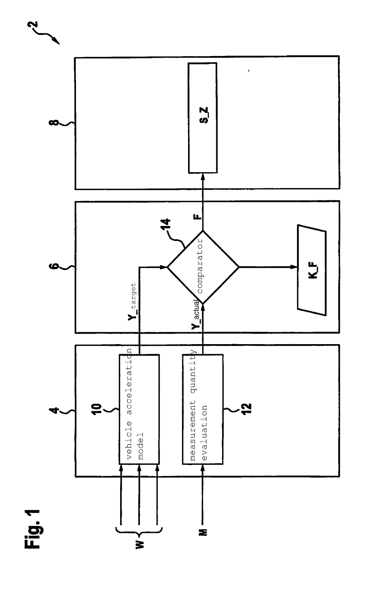
[0039]FIG. 1 schematically shows the design of an exemplary monitoring system 2 of a drive-by-wire system of a motor vehicle, having for example an internal combustion engine, an electric motor, or a hybrid drive as drive. With the drive-by-wire system, driver commands of the motor vehicle driver are electrically forwarded, via drive-by-wire, from operating elements, such as gas pedal, brake pedal, gearshift lever, or steering wheel, to the corresponding actuating elements of the motor vehicle, such as throttle valve, power converter, transmission, brakes, and / or steering.

[0040]Malfunctions of the drive-by-wire system can result in signals that address the actuating elements in an undesired manner and thus cause dangerous driving situations, e.g., undesired acceleration of the motor vehicle. Using monitoring system 2, the drive-by-wire system is monitored for such malfunctions. When such a malfunction has been determined, an error signal F is produced that causes the drive-by-wire s...


PUM


Abstract

A method for monitoring a drive-by-wire system of a motor vehicle, including: temporally offset reading in of at least two input values of an input quantity of an operating element of the motor vehicle; ascertaining a change over time or rate of change over time of the input quantity from the at least two read-in input values; determination of a monitored quantity for the motor vehicle operation from the change over time or rate of change over time; selection of a monitoring function on the basis of the monitored quantity; monitoring of the monitored quantity for the ascertained motor vehicle operation by the monitoring function.

Description

FIELD[0001]The present invention relates to a method for monitoring a drive-by-wire system of a motor vehicle, as well as a computing unit and a computer program for carrying out the method.BACKGROUND INFORMATION[0002]In recent developments in motor vehicle design, there is a tendency for all driver commands to be forwarded electrically only, using drive-by-wire. Drive-by-wire (DbW) designates a driving or controlling of a motor vehicle without mechanical transmission of force by operating elements, such as gas pedal, brake pedal, or steering wheel, of the motor vehicle to the corresponding actuating elements of the motor vehicle, such as the throttle valve, brakes, and / or steering of the motor vehicle. An example of a conventional DbW system is the so-called e-gas system. The controlling of the named functions takes place instead via electrical lines and servomotors or electromechanical actuators. For safety reasons, the actuating elements of the motor vehicle have to be permanentl...

Claims


Application Information

Patent Timeline
Patent Type & Authority Applications(United States)
IPC IPC(8): B60W50/04
CPCB60W50/045B60W2540/10B60W2540/12B60W2540/16B60W2540/18B60W2400/00G05B23/0229B60W50/04B60W2050/0292B60W2520/10B60W2520/06B60W2520/105B60W2520/28B60W2554/801G05B23/0235G05B23/0256G07C5/0808
Inventor GRIMM, ANDREASMUELLER, BERNDBALLMANN, EVGENIYACORRAL PATINO, ISIDROREICHERT, MARKUSHUFNAGEL, SIMONHARTGEN, THOMASMAUER, THOMAS
Owner ROBERT BOSCH GMBH
Why Eureka
Try Eureka