Projection device and method for holographic reconstruction of scenes

a projection device and holographic reconstruction technology, applied in the field of projection devices for holographic reconstruction of scenes, can solve the problems of large size limitations of micro-displays, interference of light emitted by holograms in scene objects, and difficulty in viewing scenes with both eyes, etc., to achieve simple reconstruction, high quality, and low cost

Active Publication Date: 2016-12-06
SEEREAL TECHNOLOGIES
View PDF13 Cites 0 Cited by
  • Summary
  • Abstract
  • Description
  • Claims
  • Application Information

AI Technical Summary

Benefits of technology

[0010]Now, the object of the present invention is to provide a projection device for the holographic reconstruction of two- and three-dimensional scenes which eliminates the above-mentioned disadvantages exhibited by prior art solutions and which reconstructs and renders visible scenes of any size in a large reconstruction space so that large moving scenes can be reconstructed simply, inexpensively and with high quality using a small number of optical elements.
[0014]Such a projection device according to this invention thus only contains a small number of optical elements used for holographic reconstruction. Compared with known optical devices, only little demands are made on the quality of the optical elements. This ensures an inexpensive, simple and compact design of the projection device, while light modulators of small size may be used, such as micro SLM previously used in other projection devices. The limited size of the micro SLM also restricts the number of pixels. This reduces considerably the time needed to compute the hologram, which in turn allows commercially available computer equipment to be used.
[0017]Another advantage is that the reduction of the spatial frequency spectrum to one diffraction order and the image of that diffraction order and of the aperture as an observer window prevents any cross-talking, which would typically occur in reconstructions when using light modulators with a matrix structure. This allows to serve a left eye and a right eye of an observer one after another in a multiplex process without cross-talking. Moreover, a multiplex process with the aim to serve multiple persons only then becomes possible.
[0024]The deflection element can for example be disposed in the plane of the first imaging means in the form of a controllable optical element, which virtually shifts the spectrum like a prism. However, it is also possible to provide a deflection element near the second imaging means. This deflection element then has the effect of a prism and, optionally, the effect of a lens. Thereby, the observer window is tracked laterally and, optionally, axially. This arrangement of the deflection element near the second imaging means is particularly preferable, because the entire imaging system from the light source to the second imaging means is then a static system. This means that the optical path up to the second imaging means will always be constant. First, this minimises the demands made on that section of the optical system, because the entry pupil of the first and second imaging means can be kept at a minimum. If the micro SLM or its image was to be displaced in order to track the observer window, the entry pupil of the first and second imaging means always had to be larger. This substantially reduces the demands made on the second imaging means. Secondly, the imaging properties of that static section of the optical system can be corrected optimally. Thirdly, the image of the micro SLM does not move on the second imaging means. This makes for example the position of the reconstruction of a two-dimensional scene on the second imaging means independent of the observer position.
[0029]Aberrations result in discontinuities in the frequency spectrum and in the images, said discontinuities adversely affecting the quality of the reconstructions. When positioning the first imaging means in the Fourier plane of the micro SLM, thanks to the focusing, the first imaging means for the image only has a minimal lateral extent. This ensures aberrations of the first imaging means to be minimised. Further, it must be ensured that the first imaging means images the micro SLM in an enlarge fashion, completely and homogeneously illuminated on to the second imaging means. Aberrations of the second and, if applicable, further imaging means can be compensated by the micro SLM. Phase errors which occur in conjunction with aberrations can be corrected easily by an additional according phase shift.

Problems solved by technology

However, in holography the light which is emitted by the hologram interferes in the object points of the scene, from where it propagates naturally.
A major disadvantage of hitherto known dynamic holographic methods which involve micro displays, however, is that the size of the reconstructions or of the reconstructed scenes is greatly limited by the size of the micro displays.
Micro displays and similar light modulators have a size of few inches and, despite the relatively small pitch, still a diffraction angle which is so small that viewing a scene with both eyes is hardly possible.
At an observer distance of 50 cm, a lateral dimension of 5 cm is achieved, which does not allow the scene to be viewed with both eyes.
With this resolution, viewing is only possible in a region which is just about 3 cm wide at a distance of about 1 m, which is insufficient for the reconstructed scene to be viewed simultaneously with both eyes, i.e. in a three-dimensional way.
Further, only relatively small objects can be reconstructed because of the small dimensions of the display.
However, despite the relatively high resolution, great reflectance and low switching delays of the light modulator, this device also only allows scenes with a small size to be reconstructed and to be viewed in a very small region for the same reasons mentioned in conjunction with WO 03 / 060612.
Furthermore, DMD chips only partly suit holographic purposes due to their limited coherence.
However, the demands made on the dynamic properties of the SLM used for reconstructing the sub-holograms are high, and a flat design does not appear to be feasible.
The spatial extension of the reconstruction is limited by the small size of the light modulators used for hologram reconstruction.
The tiling method described in WO 00 / 75699 generally allows large scenes to be reconstructed, but this requires a voluminous design of the device.
Because of the large number of pixels used, the computational load required to compute the hologram and the demands made on the data transfer rate will increase substantially, which makes it rather difficult to achieve real-time reconstructions.

Method used


Image

  • Projection device and method for holographic reconstruction of scenes
  • Projection device and method for holographic reconstruction of scenes
  • Projection device and method for holographic reconstruction of scenes

Examples


Embodiment Construction

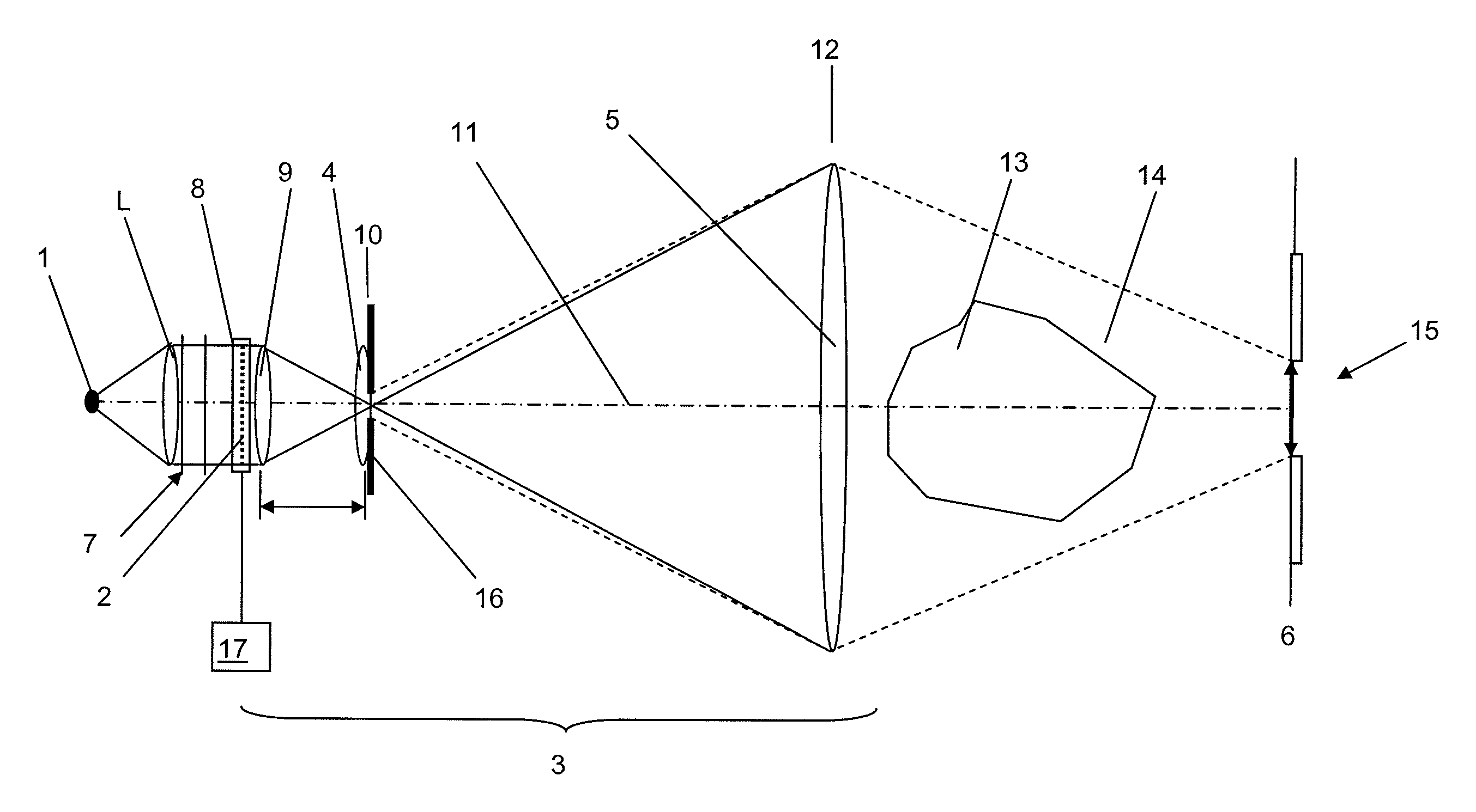
[0041]FIG. 1 shows the working principle of the projection device according to this invention, where an imaging system 3 images an illumination device 1, here a point light source, to an observer plane 6. The imaging system 3 comprises a first imaging means 4 and a second imaging means 5. The light source 1 emits coherent or sufficiently coherent light, which is required for a holographic reconstruction of a scene. The light source 1 can be a laser, LED(s) or other light sources, where colour filters can also be used.

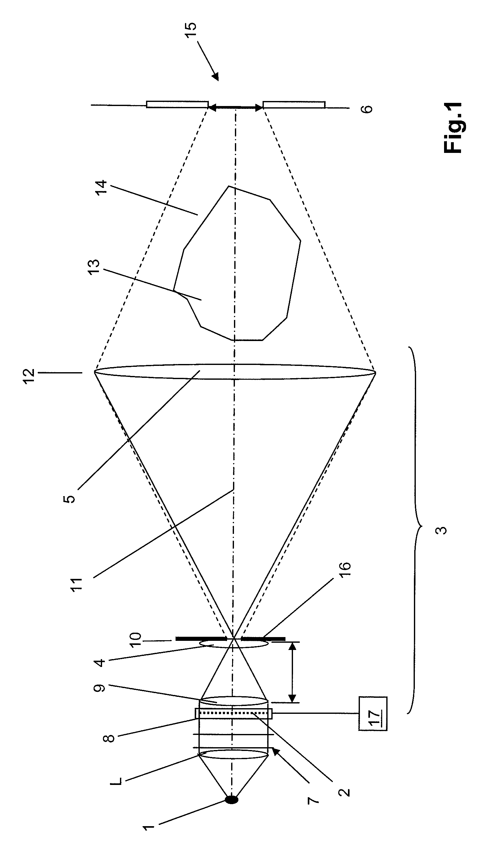
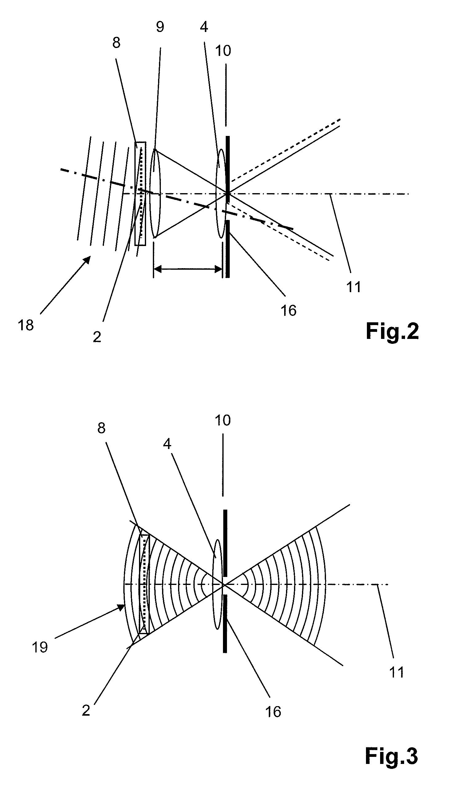
[0042]Now, the working principle of the projection device will be described with reference to FIG. 1. A wave emitted by the light source 1 is converted into a plane wave 7 with the help of a collimator lens L. The wave 7, which comes from the light source 1, and which is assumed to be plane after its passage through the collimator lens L, hits at a right angle a transmissive spatial light modulator 8 with regularly arranged pixels, which represents an encoded dynamic ho...


PUM


Abstract

A holographic reconstruction of scenes includes a light modulator, an imaging system with at least two imaging means and an illumination device with sufficient coherent light for illumination of hologram coded in the light modulator. The at least two imaging means are arranged such that a first imaging means is provided for the magnified imaging of the light modulator on a second imaging means. The second imaging means is provided for imaging of a plane of a spatial frequency spectrum of the light modulator in a viewing plane at least one viewing window. The viewing window corresponds to a diffraction order of the spatial frequency spectrum.

Description

CROSS-REFERENCE TO RELATED APPLICATIONS[0001]This is a divisional of U.S. application Ser. No. 11 / 914,278, filed Nov. 13, 2007, which is the US national stage of International Application No. PCT / DE2006 / 000896, filed May 12, 2006, which claims priority to German Application No. DE 10 2005 023 743.6, filed on May 13, 2005, the entire contents of each of which being fully incorporated herein by reference.BACKGROUND OF THE INVENTION[0002]The present invention relates to a projection device for the holographic reconstruction of scenes, said device comprising a spatial light modulator, an imaging system with at least two imaging means and an illumination system with at least one light source to generate sufficiently coherent light for the illumination of a hologram encoded on the light modulator. This invention further relates to a method for the holographic reconstruction of scenes.[0003]Known 3D displays or 3D projection devices and methods usually take advantage of the stereo effect, ...

Claims


Application Information

Patent Timeline
Patent Type & Authority Patents(United States)
IPC IPC(8): G03H1/08G02B5/32G03H1/10G02B5/18G03H1/22G03H1/16
CPCG03H1/0866G03H1/16G03H1/2202G03H1/2294G02B5/1876G03H1/2249G03H2001/0883G03H2001/221G03H2001/226G03H2001/2239G03H2001/2242G03H2001/2271G03H2210/30G03H2222/54G03H2223/18G03H2223/19G03H2223/24G03H2225/52G03H2225/61G03H2226/05H04N5/74G03H1/22H04N13/00
Inventor SCHWERDTNER, ARMIN
Owner SEEREAL TECHNOLOGIES
Why Eureka
Try Eureka