Implant delivery device

a technology of implanted devices and stents, which is applied in the field of implanted devices, can solve the problems of user position, low stability, and low flexibility of micro-coils, and achieve the effect of minimizing the surface temperature of the device and short detachment tim

Active Publication Date: 2017-02-07
MICROVENTION INC
View PDF206 Cites 185 Cited by
  • Summary
  • Abstract
  • Description
  • Claims
  • Application Information

AI Technical Summary

Benefits of technology

[0012]In another aspect of the present invention, the tether detachably coupling the implant to the pusher acts as a reservoir of stored (i.e. potential) energy that is released during detachment. This advantageously lowers the time and energy required to detach the implant because it allows the tether to be severed by application of heat without necessarily fully melting the material. The stored energy also may exert a force on the implant that pushes it away from the delivery catheter. This separation tends to make the system more reliable because it may prevent the tether from re-solidifying and holding the implant after detachment. Stored energy may be imparted in several ways. In one embodiment, a spring is disposed between the implant and pusher. The spring is compressed when the implant is attached to the pusher by joining one end of the tether to one of either the pusher or implant, pulling the free end of the tether until the spring is at least partially compressed, then affixing the free end of the tether to the other of the implant or the pusher. Since both ends of the tether are restrained, potential energy in the form of tension on the tether (or compression in the spring) is stored within the system. In another embodiment, one end of the tether is fixed as in the previous embodiment, and then the tether is placed in tension by pulling on the free end of the tether with a pre-determined force or displacement. When the free end of the tether is then affixed, the elongation (i.e. elastic deformation) of the tether material itself stores energy.
[0015]In another aspect of the present invention, the core mandrel is in the form of a solid or hollow shaft, wire, tube, hypotube, coil, ribbon, or combination thereof. The core mandrel may be made from plastic materials such as PEEK, acrylic, polyamide, polyimide, Teflon, acrylic, polyester, block copolymer such as PEBAX, or the like. The plastic member(s) may be selectively stiffened along the length with reinforcing fibers or wires made from metal, glass, carbon fiber, braid, coils, or the like. Alternatively, or in combination with plastic components, metallic materials such as stainless steel, tungsten, chromium cobalt alloy, silver, copper, gold, platinum, titanium, nickel titanium alloy (Nitinol), and the like may be used to form the core mandrel. Alternatively, or in combination with plastic and / or metallic components, ceramic components such as glass, optical fiber, zirconium, or the like may be used to form the core mandrel. The core mandrel may also be a composite of materials. In one embodiment, the core mandrel comprises an inner core of radiopaque material such as platinum or tantalum and an outer covering of kink-resistant material such as steel or chromium cobalt. By selectively varying the thickness of the inner core, radiopaque identifiers can be provided on the pusher without using secondary markers. In another embodiment, a core material, for example stainless steel, with desirable material properties such as kink resistance and / or compressive strength is selectively covered (by, for example, plating, drawing, or similar methods known in the art) with a low electrical resistance material such as copper, aluminum, gold, or silver to enhance its electrical conductivity, thus allowing the core mandrel to be used as an electrical conductor. In another embodiment, a core material, for example, glass or optical fiber, with desirable properties such as compatibility with Magnetic Resonance Imaging (MRI), is covered with a plastic material such as PEBAX or polyimide to prevent the glass from fracturing or kinking.
[0020]In another aspect of the present invention, the power source may comprise an electronic circuit that assists the user with detachment. In one embodiment, the circuit detects detachment of the implant and provides a signal to the user when detachment has occurred. In another embodiment, the circuit comprises a timer that provides a signal to the user when a pre-set length of time has elapsed. In another embodiment, the circuit monitors the number of detachments and provides a signal or performs an operation such as locking the system off when a pre-set number of detachments have been performed. In another embodiment, the circuit comprises a feedback loop that monitors the number of attachment attempts and increases the current, voltage, and / or detachment time in order to increase the likelihood of a successful detachment.
[0021]In another aspect of the present invention, the construction of the system allows for extremely short detachment time. In one embodiment the detachment time is less than 1 second.
[0022]In another aspect of the present invention, the construction of the system minimizes the surface temperature of the device during detachment. In one embodiment, the surface temperature at the heater during detachment is under 50° C. In another embodiment, the surface temperature at the heater during detachment is under 42° C.

Problems solved by technology

Microcoils are extremely flexible and have very little structural integrity.
While implant delivery and detachment systems are known in the art, they do not provide the user feedback that the implant has indeed detached from the delivery device.
These delivery devices leave the user in the position of wondering whether heat etc., has been applied long enough to cause detachment.

Method used


Image

  • Implant delivery device
  • Implant delivery device
  • Implant delivery device

Examples


Embodiment Construction

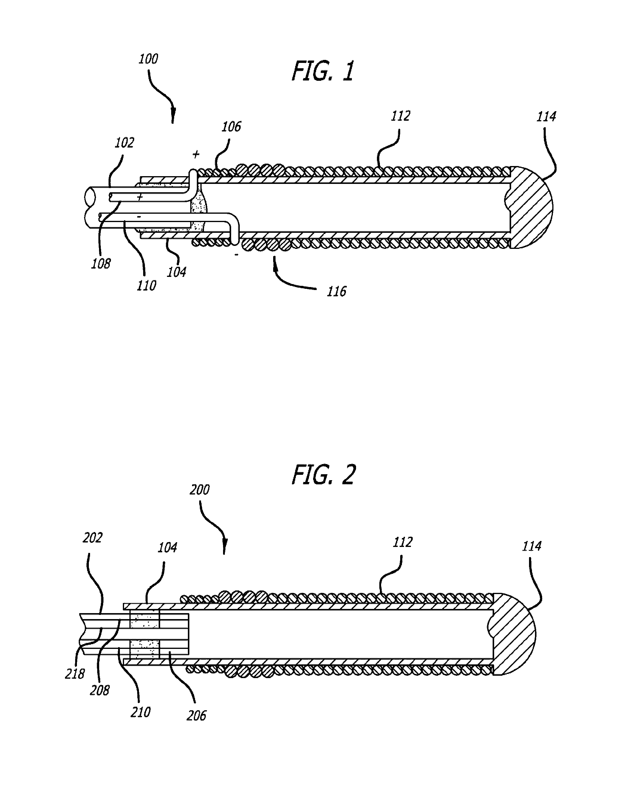
[0043]Turning to FIG. 1, a detachment system 100 of the present invention, and specifically the distal portion of the detachment system 100, is illustrated. The detachment system 100 includes a pusher 102 that is preferably flexible. The pusher 102 is configured for use in advancing an implant device 112 into and within the body of a patient and, specifically, into a target cavity site for implantation and delivery of the implant device 112. Potential target cavity sites include but are not limited to blood vessels and vascular sites (e.g., aneurysms and fistula), heart openings and defects (e.g., the left atrial appendage), and other luminal organs (e.g., fallopian tubes).

[0044]A stretch-resistant tether 104 detachably couples the implant 112 to the pusher 102. In this example, the tether 104 is a plastic tube that is bonded to the pusher 102. A substantially solid cylinder could also be a design choice for the tether 104. The stretch resistant tether 104 extends at least partially...


PUM


Abstract

A system for delivering an implant within a patient is described. The activation of the heater coil causes the degradation, melting or reduction of a component that brings the heater coil into or out of electrical contact with another component, or causes the individual loops of the coil to contact each other, thereby resulting a notable change in resistance in the circuit supplying the heater coil with electricity. A core wire terminates prior to the distal end of the device, allowing for greater flexibility.

Description

RELATED APPLICATIONS[0001]This application claims priority to U.S. Provisional Application Ser. No. 61 / 324,246 filed Apr. 14, 2010 entitled Implant Delivery Device, the contents of which are hereby incorporated by reference.FIELD OF THE INVENTION[0002]The present invention relates to systems and methods for delivering implant devices to a target site or location within the body of a patient. The present invention also relates to a method of detecting implant detachment within the body of a patient.BACKGROUND OF THE INVENTION[0003]Delivery of implantable therapeutic devices by less invasive means has been demonstrated to be desirable in numerous clinical situations. For example, vascular embolization has been used to control vascular bleeding, to occlude the blood supply to tumors, to occlude fallopian tubes, and to occlude vascular aneurysms, particularly intracranial aneurysms. In recent years, vascular embolization for the treatment of aneurysms has received much attention. Implan...

Claims


Application Information

Patent Timeline
Patent Type & Authority Patents(United States)
IPC IPC(8): A61F2/82A61F2/95A61B17/00A61B17/12
CPCA61F2/95A61B17/1214A61B17/12027A61B17/12099A61B17/12154A61B2017/00867A61B2017/1209A61B2017/12054A61B2017/12068A61B2017/12072A61B2017/12077A61F2002/9505A61B17/00A61M25/01A61B2090/3966A61B17/12113A61B17/12122A61B2017/00119A61B2017/00477A61B2017/00734A61B2017/4233A61M25/0021A61M2025/0042
Inventor BOWMAN, HEATHLE, JAKEFITZ, MATTHEW
Owner MICROVENTION INC
Why Eureka
Try Eureka