Liquid crystal display device

a liquid crystal display and display device technology, applied in the direction of liquid crystal compositions, instruments, chemistry apparatus and processes, etc., can solve the problems of reducing defective display, and the technique is substantially not different from merely reducing, so as to prevent the decrease of the voltage holding ratio of the liquid crystal layer, eliminate the defect of the display, and prevent the increase of the ion density.

Active Publication Date: 2017-06-20
DIC CORPORATION +1
View PDF35 Cites 0 Cited by
  • Summary
  • Abstract
  • Description
  • Claims
  • Application Information

AI Technical Summary

Benefits of technology

[0023]In the liquid crystal display device of the present invention, using a specific liquid crystal composition and a color filter in which a specific pigment is used enables prevention of a decrease in the voltage holding ratio (VHR) of a liquid crystal layer, prevention of an increase in ion density (ID) therein, and elimination of defective display such as dropouts, uneven alignment, and screen burn-in.

Problems solved by technology

Hence, the color filter layer and the liquid crystal layer are not in a state in which they are completely isolated from each other, and the color filter layer may therefore cause problems due to impurities which are contained in the color filter layer and which pass through the alignment film and the transparent electrode, such as a decrease in the voltage holding ratio (VHR) of the liquid crystal layer and defective display, e.g., dropouts due to increased ion density (ID), uneven alignment, and screen burn-in.
These techniques, however, are substantially not different from merely reducing the impurity content in a pigment and are insufficient to overcome defective display even in a current situation in which a technique for purifying pigments has been advanced.
Also in such disclosure, however, the technique is substantially for reducing effects of impurities present in a pigment on the liquid crystal layer, and a direct relationship between the structure of a colorant, such as a dye or a pigment, used for the color filter layer and the structure of a liquid crystal material is not considered; thus, problems of defective display in highly-developed liquid crystal display devices have not been overcome.

Method used


Image

  • Liquid crystal display device
  • Liquid crystal display device
  • Liquid crystal display device

Examples


examples

[0230]Although some best modes of the present invention will now be described in detail with reference to Examples, the present invention is not limited to Examples. In compositions which will be described in Examples and Comparative Examples, the term “%” refers to “mass %”.

[0231]In Examples, the following properties were measured.

[0232]Tni: nematic phase-isotropic liquid phase transition temperature (° C.)

[0233]Δn: refractive index anisotropy at 25° C.

[0234]ΔE: dielectric constant anisotropy at 25° C.

[0235]η: viscosity at 20° C. (mPa·s)

[0236]γ1: rotational viscosity at 25° C. (mPa·s)

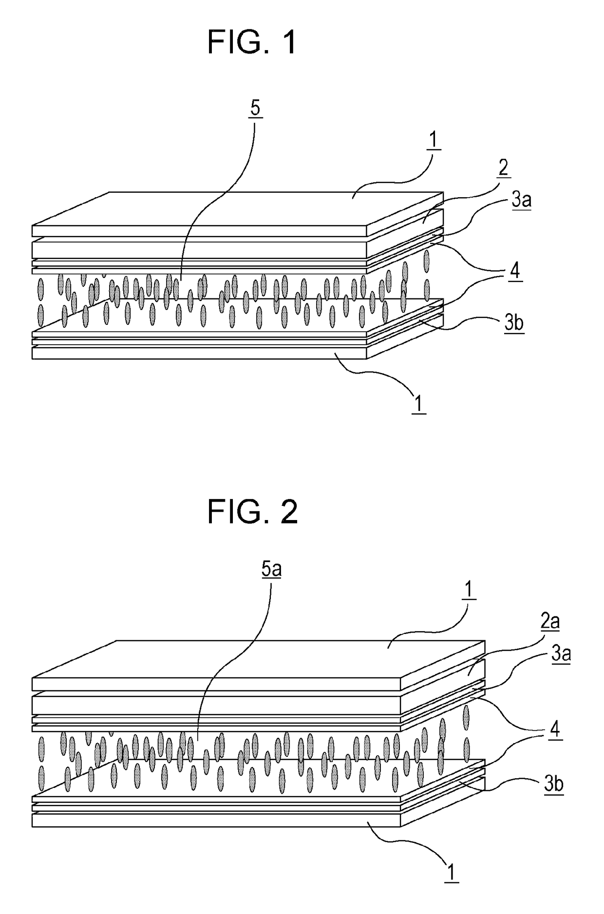
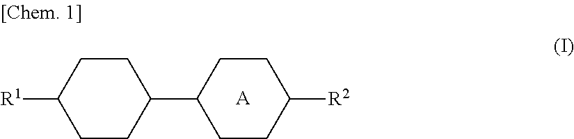
[0237]dgap: gap between first and second substrates in cell (μm)

[0238]VHR: voltage holding ratio at 70° C.

[0239](ratio, represented by %, of measured voltage to initial applied voltage, which was obtained as follows: a liquid crystal composition was put into a cell having a thickness of 3.5 μm, and the measurement was carried out under the conditions of applied voltage of 5 V, frame time of 200 ms and ...

examples 1 to 4

[0308]Electrodes corresponding to first and second substrates were formed, vertical alignment films were formed on the facing surfaces thereof, the alignment films were slightly rubbed to form VA cells, and then a liquid crystal composition 1 shown in Table 10 was placed between the first and second substrates. Then, the color filters 1 to 4 shown in Table 8 were used to produce liquid crystal display devices of Examples 1 to 4 (dgap=3.5 μm and alignment film SE-5300). The VHR and ID of the produced liquid crystal display devices were measured. The screen burn-in of each liquid crystal display device was evaluated. Table 11 shows results of the measurement and evaluation.

[0309]

TABLE 10Liquid crystal composition 1TNI / ° C.81.0Δn0.103Δε−2.9η / mPa · s20.3γ1 / mPa · s112γ1 / Δn2 × 10−21053-Cy-Cy-224% 3-Cy-Cy-410% 3-Cy-Cy-55%3-Cy-Ph—O12%3-Cy-Ph5—O213% 2-Cy-Ph—Ph5—O29%3-Cy-Ph—Ph5—O29%3-Cy-Cy-Ph5—O35%4-Cy-Cy-Ph5—O26%5-Cy-Cy-Ph5—O25%3-Ph—Ph5—Ph-26%4-Ph—Ph5—Ph-26%

[0310]

TABLE 11Example 1Example 2Ex...

examples 5 to 12

[0313]As in Example 1, liquid crystal compositions shown in Table 12 were placed, the color filters shown in Table 8 were used to produce liquid crystal display devices of Examples 5 to 12, and the VHR and ID thereof were measured. The screen burn-in of each liquid crystal display device was evaluated. Tables 13 and 14 show results of the measurement and evaluation.

[0314]

TABLE 12Liquid crystal composition 2TNI / ° C.76.0Δn0.103Δε−2.9η / mPa · s19.8γ1 / mPa · s110γ1 / Δn2 × 10−21033-Cy-Cy-224% 3-Cy-Cy-410% 3-Cy-Ph—O17%3-Cy-Ph5—O214% 2-Cy-Ph—Ph5—O27%3-Cy-Ph—Ph5—O29%3-Cy-Cy-Ph5—O35%4-Cy-Cy-Ph5—O27%5-Cy-Cy-Ph5—O25%3-Ph—Ph5—Ph-26%4-Ph—Ph5—Ph-26%Liquid crystal composition 3TNI / ° C.84.8Δn0.103Δε−2.9η / mPa · s21.4γ1 / mPa · s119γ1 / Δn2 × 10−21123-Cy-Cy-224% 3-Cy-Cy-411% 3-Cy-Ph5—O212% 2-Cy-Ph—Ph5—O25%3-Cy-Ph—Ph5—O26%3-Cy-Cy-Ph5—O38%4-Cy-Cy-Ph5—O28%5-Cy-Cy-Ph5—O28%3-Ph—Ph5—Ph-26%4-Ph—Ph5—Ph-26%5-Ph—Ph-13%3-Cy-Cy-Ph-13%

[0315]

TABLE 13Example 5Example 6Example 7Example 8LiquidLiquidLiquidLiquidLiquidcrysta...


PUM

PropertyMeasurementUnit
particle sizeaaaaaaaaaa
temperatureaaaaaaaaaa

Abstract

There is provided a liquid crystal display device which prevents a decrease in the voltage holding ratio (VHR) of a liquid crystal layer and an increase in ion density (ID) therein and which overcomes problems of defective display such as dropouts, uneven alignment, and screen burn-in. The liquid crystal display device of the present invention prevents a decrease in the voltage holding ratio (VHR) of a liquid crystal layer and an increase in ion density (ID) therein and reduces defective display such as screen burn-in; hence, such a liquid crystal display device is properly used as liquid crystal display devices of a VA mode and PSVA mode which involve active matrix driving and can be applied to liquid crystal display devices of liquid crystal TV sets, monitors, mobile phones, and smartphones.

Description

TECHNICAL FIELD[0001]The present invention relates to a liquid crystal display device.BACKGROUND ART[0002]Liquid crystal display devices have been applied to, for example, watches, calculators, a variety of household electrical appliances, measuring equipment, panels used in automobiles, word processors, electronic notebooks, printers, computers, and television sets. Representative examples of types of liquid crystal display devices include a TN (twisted nematic) type, an STN (super twisted nematic) type, a DS (dynamic scattering) type, a GH (guest•host) type, an IPS (in-plane switching) type, an OCB (optically compensated birefringence) type, an ECB (electrically controlled birefringence) type, a VA (vertical alignment) type, a CSH (color super homeotropic) type, and an FLC (ferroelectric liquid crystal) type. Regarding a drive system, multiplex driving has become popular instead of typical static driving; a simple matrix, in particular, an active matrix (AM) in which, for example,...

Claims


Application Information

Patent Timeline
Patent Type & Authority Patents(United States)
IPC IPC(8): G02F1/1333C09K19/32C09K19/30G02F1/1335C09K19/44G02B5/20G02B5/22C09K19/12C09K19/04C09K19/52
CPCC09K19/322C09K19/3003C09K19/3066C09K19/44G02F1/133512G02F1/133514C09K2019/3004C09K2019/3009C09K2019/3016C09K2019/3027C09K2019/523G02B5/20G02B5/22C09K2019/0448C09K2019/122C09K2019/123C09K2019/301G02F1/13G02F1/1335
Inventor OGAWAIWASHITA, YOSHINORIFUNAKURA, SEIJISHIMADA, KATSUNORI
Owner DIC CORPORATION
Why Eureka
Try Eureka