AI technical title is built by Patsnap AI team. It summarizes the technical point description of the patent document.
a flow meter and flow tube technology, applied in the field of flow meter, can solve the problems of changing the size of the lumen, the inability to use the pump in all situations or environments, etc., and achieve the effect of reducing the internal volume of the fluid tub
Active Publication Date: 2017-08-08
DEKA PROD LLP
View PDF460 Cites 73 Cited by
Summary
Abstract
Description
Claims
Application Information
AI Technical Summary
This helps you quickly interpret patents by identifying the three key elements:
Problems solved by technology
Method used
Benefits of technology
Benefits of technology
[0030]In certain embodiments of the present disclosure, the apparatus includes an actuator operatively coupled to the curved, elongated support member at the first and second ends, and to the another curved, elongated support member at first and second ends. The actuation of the actuator causes the first and second ends of the curved, elongated support member to approach each other and also causes the first and second ends of the another curved, elongated support member to approach each other to thereby cause a reduction in distance between the curved, elongated support member and the another curved, elongated support member to thereby compress the tube.
[0233]In another embodiment, a method of filtering a captured image of a drip chamber configured to allow a drop of fluid to fall within the drip chamber, the method comprising: capturing an image of the drip chamber with an image sensor; determining if the captured image contains a visual obstruction; applying a blurring function to the captured image, the blurring function configured to eliminate an amount of detail in the captured image; and determining if the captured image contains a match to a template.
Problems solved by technology
Typically, such applications use an infusion pump, but such pumps may not be used in all situations or environments.
Changes in displacement by the plunger alter the forces on the section of the tube within the casing resulting in the lumen changing size.
Method used
Image
Click on the blue label to locate the original text in one second.
Reading with bidirectional positioning of images and text.
Examples
Embodiment Construction
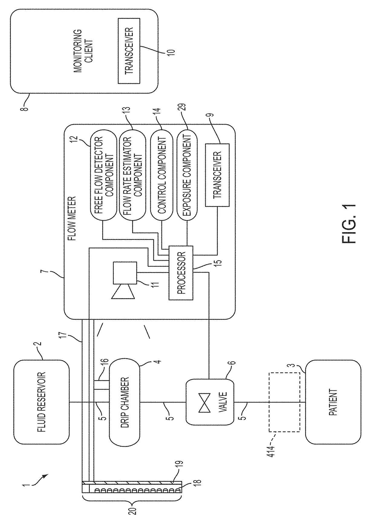
[0343]FIG. 1 shows a block diagram of a system 1 for regulating fluid flow in accordance with an embodiment of the present disclosure. For example, system 1 may regulate, monitor, and / or control the flow of fluid into a patient 3. The system 1 includes a fluid reservoir 2 for infusing fluid contained therein into the patient 3. The fluid reservoir 2 is gravity fed into a drip chamber 4 via a fluid tube 5. The fluid reservoir 2, the drip chamber 4, and the patient 3 may be considered as part of the system 1 or may be considered as separate or optional work pieces for the system 1 (e.g., any fluid reservoir 2 and drip chamber 4 may be used to treat any patient 3).
[0344]A flow meter 7 monitors the drip chamber 4 to estimate a flow rate of liquid flowing through the drip chamber 4. The fluid from the drip chamber 4 is gravity fed into a valve 6. The valve 6 regulates (i.e., varies) the flow of fluid from the fluid reservoir 2 to the patient 3 by regulating fluid flow from the drip chamb...
PUM
Abstract
An flow meter includes a coupler, a support member, an image sensor, and one or more processors. The coupler is adapted to couple to a drip chamber. The support member is operatively coupled to the coupler. The image sensor has a field of view and is operatively coupled to the support member. The image sensor is positioned to view the drip chamber within its field of view. The one or more processors are operatively coupled to the image sensor to receive data therefrom. The one or more processors (1) receive image data from the image sensor, and (2) determine an existence of a free flow condition by identifying an optical distortion of an area behind the free flow condition within the drip chamber using the received image data.
Description
CROSS REFERENCE TO RELATED APPLICATIONS[0001]The present application is a Continuation Application of U.S. patent application Ser. No. 14 / 213,373, filed Mar. 14, 2014 and entitled System, Method, and Apparatus for Monitoring, Regulating, or Controlling Fluid Flow which is a Continuation-In-Part of U.S. patent application Ser. No. 13 / 834,030, filed Mar. 15, 2013 and entitled System, Method, and Apparatus for Monitoring, Regulating, or Controlling Fluid Flow, now U.S. Publication No. US-2013-0310990-A1, published Nov. 21, 2013, which is a Continuation-In-Part application of U.S. patent application Ser. No. 13 / 723,244, filed Dec. 21, 2012 and entitled System, Method, and Apparatus for Monitoring, Regulating, or Controlling Fluid Flow, now U.S. Publication No. US-2013-0188040-A1, published Jul. 25, 2013, which claims priority to and the benefit of the following:[0002]U.S. Provisional Patent Application Ser. No. 61 / 578,649, filed Dec. 21, 2011 and entitled System, Method, and Apparatus f...
Claims
Application Information
Patent Timeline
Application Date:The date an application was filed.
Publication Date:The date a patent or application was officially published.
First Publication Date:The earliest publication date of a patent with the same application number.
Issue Date:Publication date of the patent grant document.
PCT Entry Date:The Entry date of PCT National Phase.
Estimated Expiry Date:The statutory expiry date of a patent right according to the Patent Law, and it is the longest term of protection that the patent right can achieve without the termination of the patent right due to other reasons(Term extension factor has been taken into account ).
Invalid Date:Actual expiry date is based on effective date or publication date of legal transaction data of invalid patent.

