Device for heating a fluid

a fluid heating and fluid technology, applied in the direction of combustion types, lighting and heating apparatus, machines/engines, etc., can solve the problems of affecting the efficiency of such a method, affecting the heating effect of the device, etc., and achieve the effect of simple assembly

Inactive Publication Date: 2017-10-31
ARIANEGRP SAS
View PDF10 Cites 0 Cited by
  • Summary
  • Abstract
  • Description
  • Claims
  • Application Information

AI Technical Summary

Benefits of technology

[0009]In this way, even though the first combustion is not performed under stoichiometric conditions, and thus even though unburnt excess propellant is present in the first burnt gas, it is possible to consume some of this unburnt propellant in the second burner unit by performing combustion with the limiting propellant; the amount of the propellant in excess that is lost is therefore reduced correspondingly.
[0031]In certain embodiments, the overall heat exchanger is made up of two half-casings that are assembled together and provided with seals. These two half-casings may be assembled together so that they contain all of the burnt gas tubes. This embodiment is particularly simple to assemble.

Problems solved by technology

Nevertheless, since such combustion is highly exothermic, it is not possible to perform it under stoichiometric conditions, since the combustion would release too much heat leading to temperatures that are too high, and thus damaging the materials of the burner or of the heat exchanger.
The efficiency of such a method is therefore rather low: a significant amount of payload propellant thus ends up being lost.
Given the constraints in terms of weight and volume for such a launcher, it can be understood that such a method is not satisfactory.

Method used


Image

  • Device for heating a fluid
  • Device for heating a fluid

Examples


Embodiment Construction

[0043]In order to make the invention more concrete, an example device is described below in detail with reference to the accompanying drawing. It should be understood that the invention is not limited to this example.

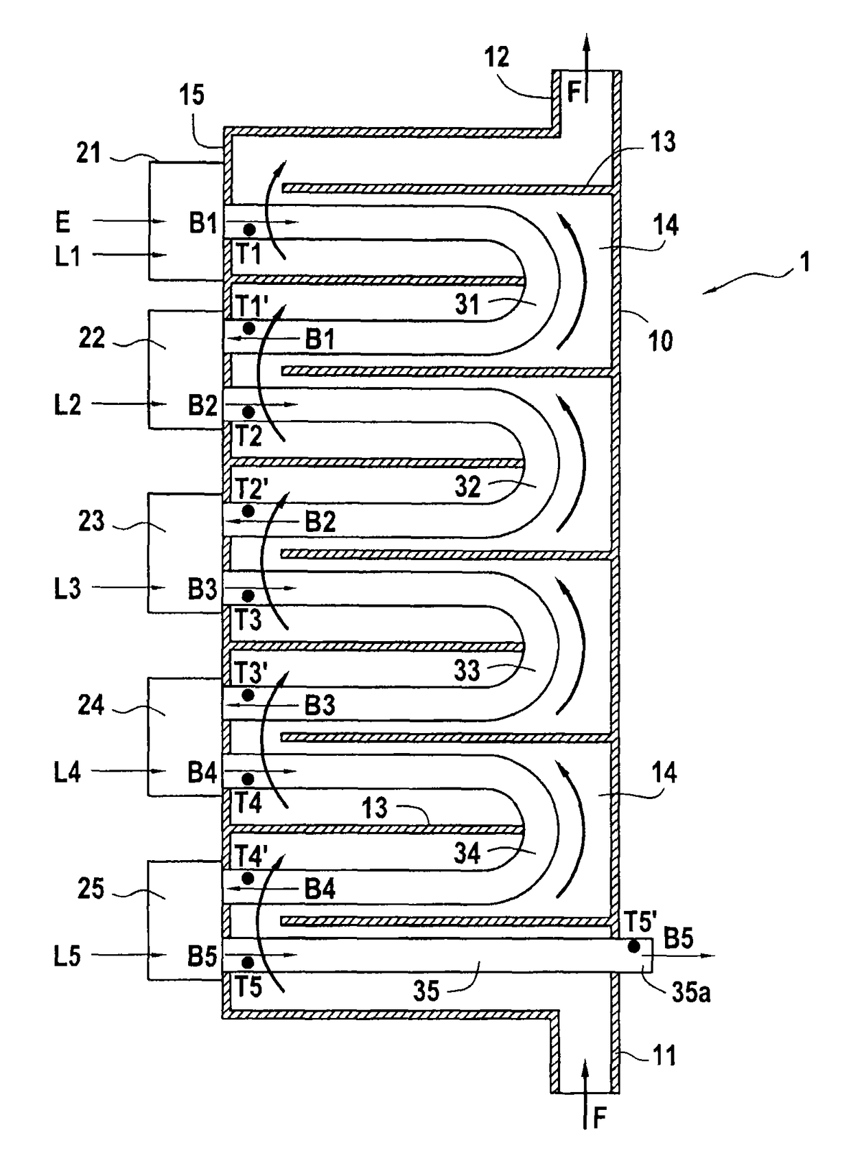
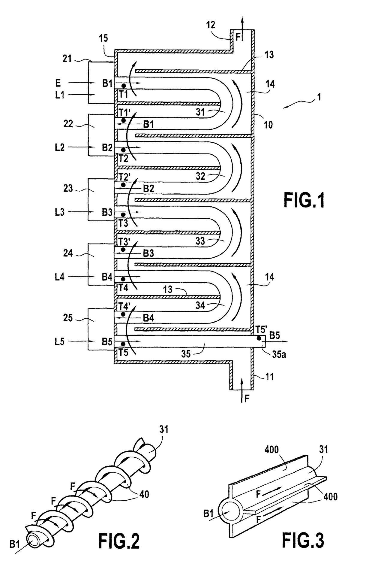
[0044]FIG. 1 is a diagrammatic section view of the device 1. The device 1 comprises an overall heat exchanger 10, a first burner 21, and four other burners 22, 23, 24, and 25.

[0045]The overall heat exchanger 10 has an inlet orifice 11, an outlet orifice 12, and a plurality of internal partitions 13. The fluid F for vaporizing penetrates into the overall heat exchanger 10 via the inlet orifice 11, flows along the passage 14 defined by the partitions 13, and leaves the overall heat exchanger 10 via the outlet orifice 12. The array of partitions 13 may be oriented in three dimensions so as to force the fluid F to travel along a longer path in the passage 14 between the inlet orifice 11 and the outlet orifice 12. Both arrows in FIG. 1 show the path followed by the fluid F i...


PUM


Abstract

A device heating a fluid and usable in a rocket launcher to pressurize a liquefied propellant. The device includes a first burner performing first combustion between a limiting propellant and an excess propellant; a first heat exchanger in which first burnt gas from the first combustion transfers heat to the fluid; at least one second burner into which both the first burnt gas and some limiting propellant are injected to perform second combustion between the limiting propellant and at least a portion of unburnt excess propellant present in the first burnt gas. The second burnt gas from the second combustion flows through a second heat exchanger to transfer heat to the fluid. Burnt gas from each combustion flows in respective burnt gas tubes within a common overall heat exchanger including the heat exchange units, the gas transferring heat to the fluid, the fluid flowing between the burnt gas tubes.

Description

FIELD OF THE INVENTION[0001]The invention relates to a device for heating a fluid in order to heat a liquefied fluid, in particular in order to vaporize it and to superheat it; the invention also relates to a rocket launcher including such a device.[0002]Such a device may be used in particular for vaporizing a fluid that is it desired to use in gaseous form: the device may typically be used in a rocket launcher for pressurizing a liquid propellant before it is injected into the combustion chamber.STATE OF THE PRIOR ART[0003]In numerous rocket launchers, the propellants used for propulsion are liquids, typically liquid dihydrogen (LH2) and liquid dioxygen (LO2), and they are therefore stored in the liquid state in tanks. In such launchers, the tanks for the liquefied propellants are normally depressurized during stages of ballistic flight; nevertheless if the thruster is to be restarted after such a ballistic stage, the liquid propellant tanks need to be repressurized in order for th...

Claims


Application Information

Patent Timeline
Patent Type & Authority Patents(United States)
IPC IPC(8): F02K9/50F28D7/00F02K9/60F28D7/16F28F1/36F28F1/16F28D7/06F28F9/22F23C6/04F28D21/00
CPCF02K9/50F02K9/60F23C6/04F28D7/00F28D7/06F28D7/1615F28F1/36F28F9/22F28F1/16F28D2021/0026F23C2201/40F23C2201/401F23C2900/06041F28D7/08
Inventor VUILLAMY, DIDIERBARTHOULOT, JEAN-LUCSANNINO, JEAN-MICHEL
Owner ARIANEGRP SAS
Why Eureka
Try Eureka