

Variable Capacity Vane Pump
A vane pump, capacity technology, applied in rotary piston pumps, pumps, pump components, etc., can solve problems such as pressure rise, achieve the effect of smooth compression speed and suppress shock pressure
Patent Information
- Authority / Receiving Office
- CN · China
- Patent Type
- Patents(China)
- Current Assignee / Owner
- Publication Date
- 2018-04-06
- Estimated Expiration
- Not applicable · inactive patent
Smart Images
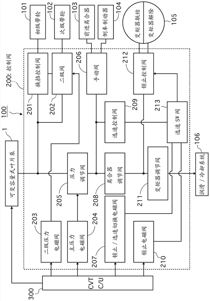
Figure 1 
Figure 2 
Figure 3
Abstract
Description
technical field
[0001] The invention relates to a variable capacity vane pump. Background technique
[0002] Conventionally, there is known a variable capacity vane pump in which vanes are accommodated in slits of a rotor so as to be able to move in and out, and the volume of a pump chamber formed between a stator inner peripheral surface, a rotor outer peripheral surface, and the vanes is varied. Patent Document 1 describes an example related to the technique described above.
[0003] Patent Document 1: (Japanese) Unexamined Patent Publication No. 2012-87777
[0004] In the conventional apparatus described above, the pressure in the pump chamber rises rapidly during low-speed rotation, and there is a need to further suppress the so-called surge pressure. Contents of the invention
[0005] An object of the present invention is to provide a variable displacement vane pump capable of suppressing shock pressure during low-speed rotation.
[0006] In the variable capacity v...
Examples
Embodiment 1
[0062] [Structure of Variable Capacity Vane Pump]
[0063] figure 1 It is a block diagram showing an example of a belt-type continuously variable transmission (CVT) 100 to which the variable displacement vane pump (hereinafter referred to as "vane pump") 1 of Embodiment 1 is applied. The outline of the vane pump (hereinafter referred to as "vane pump") 1 will be described. Vane pump 1 is used as a hydraulic pressure supply source for CVT 100 .
[0064] The vane pump 1 is driven by a crankshaft (not shown) of an internal combustion engine (engine), and sucks in / discharges a working fluid. Hydraulic oil, specifically, ATF (Automatic Transmission Fluid) is used as the working fluid. Hydraulic fluid (ATF) has a large elastic coefficient and a property in which the pressure changes greatly with a small change in volume.
[0065] In the control valve 200, various valves 201 to 213 controlled by the CVT control unit 300 are provided. The hydraulic oil discharged from the vane pu...
Embodiment 2
[0214] Figure 10 It is a graph showing the rate of change of the cam profile radius with respect to the angle for defining the stator profile when the stator eccentricity in Example 2 is the smallest.
[0215] In Example 2, such as Figure 10 As shown, the stator 8 differs from the first embodiment in that the rate of change of the cam profile radius has a negative value at the point where the stator profile definition angle is 180 degrees when the eccentricity δ of the stator 8 is the smallest.
[0216] The action of Example 2 will be described.
[0217] In the case where the stator 8 is formed such that when the stator eccentricity is the largest, the cam profile radius change rate temporarily decreases on the second confinement area side and then increases again, the smaller the eccentricity δ, the more the compression rate on the second confinement area side is suppressed or The larger the expansion ratio, the weaker the compression during high-speed rotation, and it may ...
Embodiment 3
[0223] Figure 11 It is a graph showing the change rate of the cam profile radius with respect to the angle for defining the stator profile when the stator eccentricity amount is maximum in Example 3.
[0224] In Example 3, such as Figure 11 As shown, the stator 8 is formed such that when the eccentric amount δ of the stator 8 is the largest, the maximum value when the cam profile radius change rate increases again after a temporary decrease is a negative value on the side of the second confinement area. 2 different.
[0225] The action of Example 3 will be described.
[0226] The greater the maximum value of the cam profile radius change rate when the cam profile radius change rate increases again, the larger the expansion rate is when the eccentricity δ is small. Therefore, in Example 3, by setting the cam profile radius change rate at which the maximum value is a negative value, it is possible to suppress Expansion with a small eccentricity δ can suppress cavitation dur...