Little oil gasification and burning lateral-igniting center coal powder-feeding swirling burner

A swirl burner and burner technology, which can be used in the burner, burner, combustion ignition and other directions of burning powder fuel, and can solve problems such as wear and tear

Inactive Publication Date: 2009-08-26
HARBIN INST OF TECH
View PDF6 Cites 0 Cited by
  • Summary
  • Abstract
  • Description
  • Claims
  • Application Information

AI Technical Summary

Problems solved by technology

[0004] The purpose of the present invention is to solve the problem of fuel saving when the large pulverized coal boiler using the swirl burner reduces NOx emissions at the same time when the utility boiler is started, stopped, and low-load stable combustion, and the problem of wear and tear caused by long-term use , a swirl burner with gasification combustion of a small amount of oil and powder feeding in the center of side ignition is proposed

Method used


Image

  • Little oil gasification and burning lateral-igniting center coal powder-feeding swirling burner
  • Little oil gasification and burning lateral-igniting center coal powder-feeding swirling burner

Examples


specific Embodiment approach 1

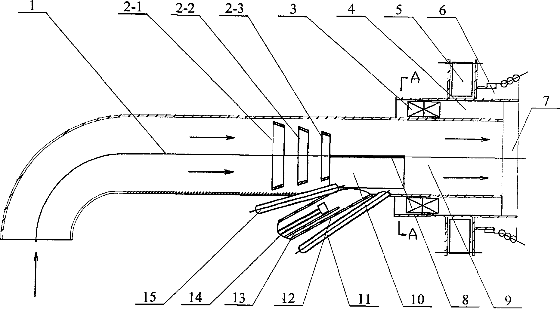
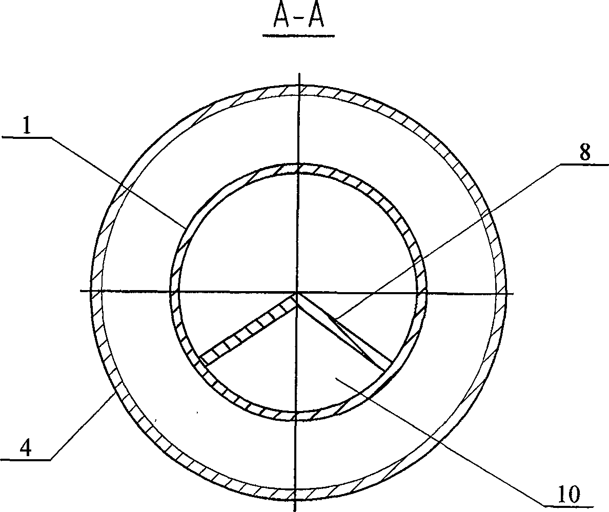
[0006] Specific implementation mode one: (see figure 1 , figure 2 ) This embodiment consists of a burner primary air duct 1, a first truncated conical separating ring 2-1, a second truncated conical separating ring 2-2, a third truncated conical separating ring 2-3, an inner swirler 3, and a burner Inner secondary air duct 4, external swirler 5, burner outer secondary air duct 6, burner 7, inverted "V"-shaped partition 8, secondary combustion chamber 9, primary combustion chamber 10, auxiliary oil gun 11. The main oil gun casing 12, the ignition gun 13, the main oil gun 14 and the flame detection tube 15. The outlet end of the primary air duct 1 of the burner is the burner 7, and the secondary air duct 4 in the burner is fixed on the burner On the outer surface of the outlet end of the primary air duct 1, the inner swirler 3 is fixed between the primary air duct 1 of the burner and the secondary air duct 4 inside the burner, and the outer swirler 5 is fixed on the secondary ...

specific Embodiment approach 2

[0007] Specific implementation mode two: (see figure 1 ) The heads of the main oil gun 14, auxiliary oil gun 11, ignition gun 13 and main oil gun casing 12 of this embodiment are arranged in the direction of the burner nozzle 7 of the primary air duct 1 of the burner. On one side, the afterbody of main oil gun 14, auxiliary oil gun 11, ignition gun 13 and main oil gun sleeve pipe 12 is warped outwards, and main oil gun 14, auxiliary oil gun 11, ignition gun 13 and main oil gun sleeve pipe 12 and The included angle of the center line of the burner is 55°~65°. Others are the same as in the first embodiment.

specific Embodiment approach 3

[0008] Specific implementation mode three: (see figure 1 ) The included angles between the main oil gun 14, the auxiliary oil gun 11, the ignition gun 13 and the main oil gun casing 12 of this embodiment and the centerline of the burner are all 60°. Others are the same as in the second embodiment.


PUM


Abstract

The invention relates to swirl-flow burner. The first, second, and third truncated cone shape separating rings are orderly set at the middle of the burner primary flue in which the backward V shape separator is fixed at the right of the third truncated cone shape separating ring. The invention can greatly reduce initiation energy, satisfy the demands of start stop, and under load stable combustion for boiler, prolong coal dust residence time, control NOx production, form fractional combustion to combine with center feeding, realize NOx low discharge owing to secondary draft is divided into inner and outer two parts.

Description

technical field [0001] The invention relates to a swirl burner. Background technique [0002] In the large-capacity power plant boilers operating in my country, the amount of oil used for boiler ignition and low-load stable combustion is huge. In order to save fuel, power generation companies shift the focus of fuel saving from the low-load stable combustion process to the boiler ignition and shutdown process (when the power plant boiler starts and stops Fuel consumption accounts for 60%, low-load stable fuel consumption accounts for 40%). According to the traditional method, the ignition oil gun is arranged in the secondary air port of the burner. The distance between the oil gun and the pulverized coal nozzle is relatively far, and the two airflows are parallel to each other. Therefore, the heat generated by the fuel oil is directly used for heating during ignition. The part of pulverized coal is relatively small, and the heat utilization rate is low, so that when the boil...

Claims


Application Information

Patent Timeline
Patent Type & Authority Patents(China)
IPC IPC(8): F23D1/02F23Q11/00F23D17/00
Inventor 李争起陈智超果志明秦裕琨
Owner HARBIN INST OF TECH
Why Eureka
Try Eureka