Device for printing plate-shaped work pieces

A workpiece and plate-shaped technology, which is applied in the field of devices for printing plate-shaped workpieces, can solve the problems such as the inability to maintain the working radius and the printing pattern tolerance.

Inactive Publication Date: 2007-10-10
ROBERT BURKE GMBH
View PDF1 Cites 0 Cited by
  • Summary
  • Abstract
  • Description
  • Claims
  • Application Information

AI Technical Summary

Problems solved by technology

However, the height deflection (Hhenschrnkung) of the printing roller (Hhenschrnkung), that is, the degree of non-parallelism in the plane defined by the axis of the printing roller, cannot be adjusted in width due to the retreat of the printing roller rolling on the workpiece surface during printing. Keep the same radius of action
However, for indirect printi

Method used


Image

  • Device for printing plate-shaped work pieces
  • Device for printing plate-shaped work pieces
  • Device for printing plate-shaped work pieces

Examples


Embodiment Construction

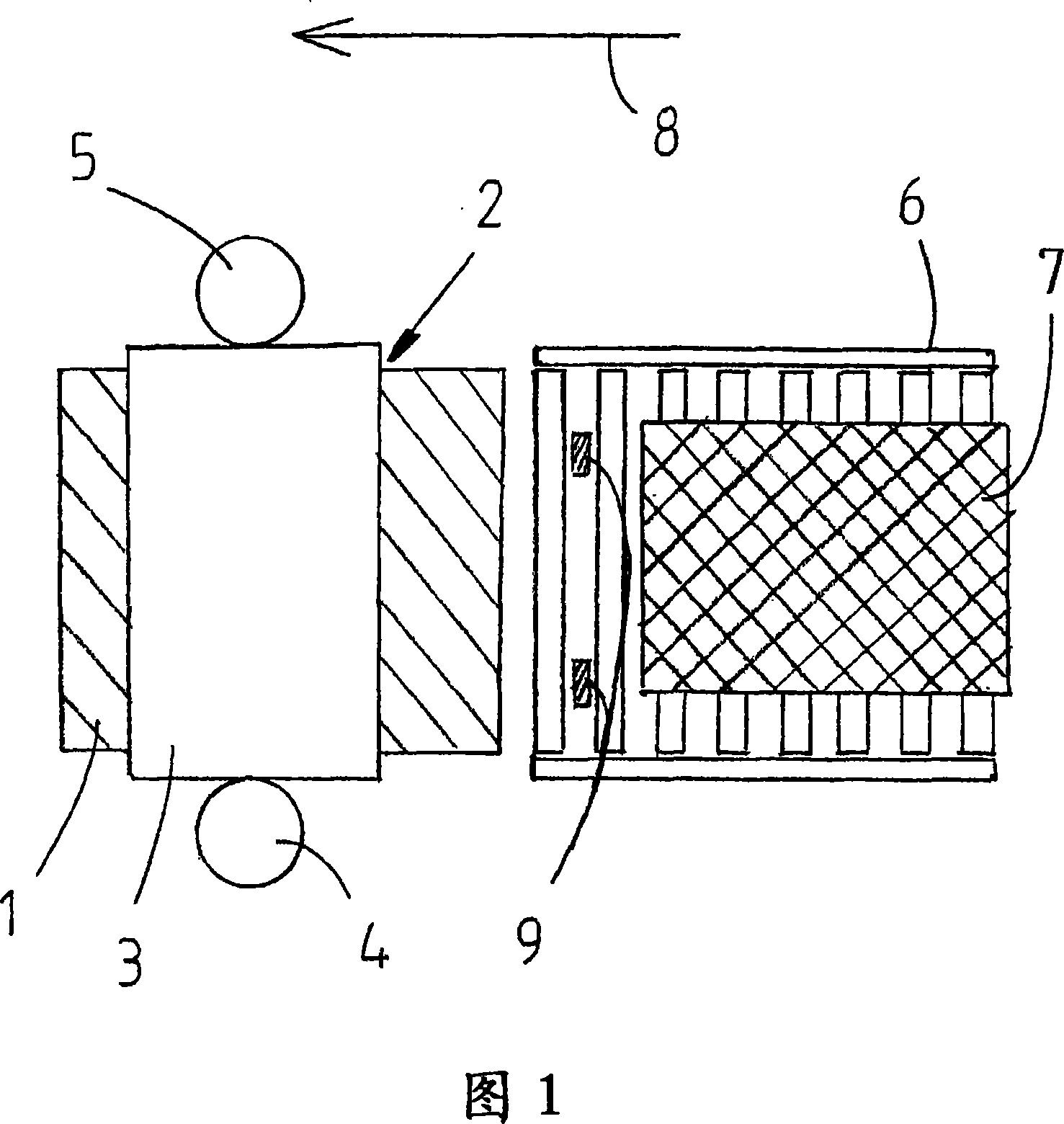
[0032] An exemplary embodiment of the device according to the invention is schematically shown in plan view in FIG. 1 . Such a device is a printing press for simple direct printing or a first printing station for a multicolor printing press, the other printing stations of which are not shown for the sake of simplicity. The conveyor belt 1 runs through a printing nip 2 formed by a printing roller 3 designed as a gravure cylinder and a corresponding printing cylinder, not visible in plan view, arranged below the conveyor belt 1 . The height of the gravure printing cylinder 3 can be adjusted by means of a left adjusting motor 4 and a right adjusting motor 5 , wherein the two adjusting motors 4 and 5 can be operated independently of one another. Plate-shaped workpieces 7 are deposited on the front rollers 6 and are guided in the direction of travel indicated by arrow 8 towards the printing nip 2 where they are transferred to the conveyor belt 1 . Before that, the workpiece passes...


PUM


Abstract

The present invention involves a method and device for printing plate-shaped workpieces during the printing gap, which is composed of two printing rollers, the distance between the printing rollers can be regulated. To print the workpieces during transporting the plate-shaped workpieces to the printing gap and drilling through the printing gap. Measuring the thickness of each workpiece before or during the transport to a printing gap, which is adjusted before the printing by parallel or slant angular changes of the gap of two press rollers together.

Description

technical field [0001] The invention relates to a method and a device for printing plate-shaped workpieces according to the preambles of claims 1 and 9 . According to this, the workpiece is printed in a printing nip formed by two printing rollers whose distance between them is adjustable. For this purpose, the plate-shaped workpiece is transported to the printing nip by a transport device. The printing rollers forming the printing nip may be printing cylinders for direct printing, applicator / transfer rollers for indirect printing and corresponding printing cylinders. Background technique [0002] Such printing methods and corresponding methods have been known for a long time. More and more recently, printing patterns of decorative patterns and textures are also applied to wood panels or the like by means of this printing method in order to give the wood panels the appearance of solid wood. This is economical not only compared to solid wood furniture, but also to the long-...

Claims


Application Information

Patent Timeline
IPC IPC(8): B41F33/14B41F13/24B41F17/08B41F33/06
CPCB41F17/26B41F13/34B41F33/0072B44F9/02
Inventor N·达姆M·波廷格尔S·莱姆勒
Owner ROBERT BURKE GMBH
Why Eureka
Try Eureka