

Rotor, axial gap type motor, driving method of motor, compressor
A technology of electric motors and rotors, applied in the field of electric motors, can solve problems such as increased cogging torque and hindering interaction
- Summary
- Abstract
- Description
- Claims
- Application Information
AI Technical Summary
Problems solved by technology
Method used
Image

Examples
no. 1 Embodiment approach
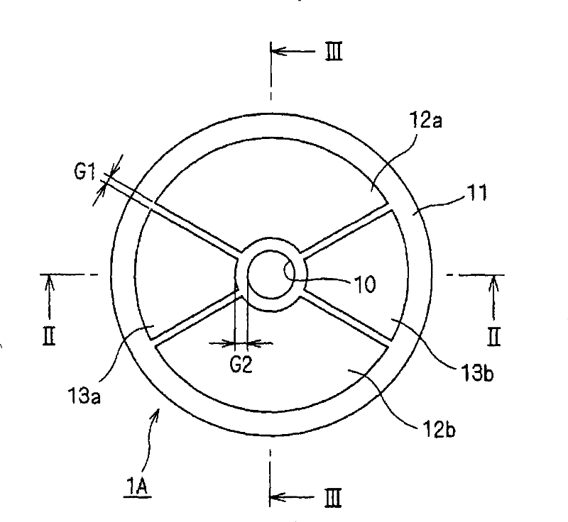
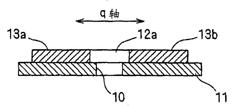
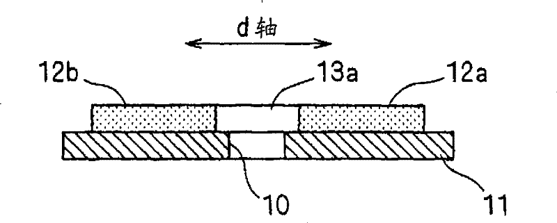
[0196] figure 1 It is a diagram illustrating the configuration of the rotor 1A according to the first embodiment of the present invention, and is a plan view of the rotor 1A seen from the stator (not shown) side when the stator constitutes a motor together with the stator. figure 2 and image 3 It is a cross-sectional view at each position II-II and position III-III.
[0197] The rotor 1A has magnets 12a, 12b, magnets 13a, 13b, and a base plate 11 on which they are placed. That is, the rotor 1A can be used as a rotor whose number of pole pairs is 1 (the number of poles is 2). At the center of the base plate 11, a shaft hole 10 is also provided.
[0198] A plurality of magnets 12a, 12b are arranged in a ring shape with polarity symmetry around the shaft hole 10, and its magnetic pole surface is perpendicular to the direction of the rotation axis (the extension direction of the rotation shaft inserted in the shaft hole 10 is parallel to the vertical direction of the paper su...
no. 2 Embodiment approach
[0215] Figure 5 It is a figure which exemplifies the structure of the rotor 1B which concerns on the 2nd Embodiment of this invention, and is a plan view which looked at the state when this rotor constitutes a motor together with a stator (not shown) from the stator side. Figure 6 and Figure 7 These are the cross-sectional views at position VI-VI and position VII-VII, respectively.
[0216] The rotor 1B has magnets 120a, 120b, magnets 130a, 130b, and a base plate 110 on which they are placed. That is, the rotor 1B may be used as a rotor having one pole pair (two poles). A shaft hole 10 is also provided at the center of the base plate 110 .
[0217] The substrate 110 and the magnets 130 a and 130 b are integrally formed using, for example, a high magnetic permeability material such as iron or dust core. That is, the substrate 110 also functions as a back yoke. It is preferable to use powdered iron cores for the substrate 110 and the magnets 130 a and 130 b from the view...
no. 3 Embodiment approach
[0234] Figure 12 It is a figure which exemplifies the structure of the rotor 1C which concerns on 3rd Embodiment of this invention, It is a top view which looked at the state which comprised the motor together with the stator (not shown) from the stator side. Figure 13 and Figure 14 Sectional views of positions XIII-XIII and positions XIV-XIV, respectively. The rotor 1C is compared to the rotor 1A shown in the first embodiment ( Figure 1 ~ Figure 3 ), has a structure in which magnetically independent magnets 14a, 14b are respectively placed on the magnetic pole surfaces of the magnets 12a, 12b to cover the magnetic pole surfaces of the magnets 12a, 12b. Here, the case where magnets 14a, 14b and magnets 12a, 12b are isomorphic is exemplified. because Figure 12 Since it is a plan view viewed from the stator side, the magnets 12a, 12b are hidden by the magnets 14a, 14b, respectively, by reference numerals 14a (12a) and 14b (12b). The magnetic pole surfaces of the rotor ...
PUM
 Abstract
Description
Claims
Application Information