
Knob solar energy lighting device
A technology of solar energy and solar cells, applied in energy-saving lighting, outdoor lighting, lighting devices, etc., can solve problems such as electric shock, injury to users, and impact on service life, achieve simple and compact structure, ensure safe use, and prolong service life Effect
- Summary
- Abstract
- Description
- Claims
- Application Information
AI Technical Summary
Problems solved by technology
Method used
Image

Examples
Embodiment 1
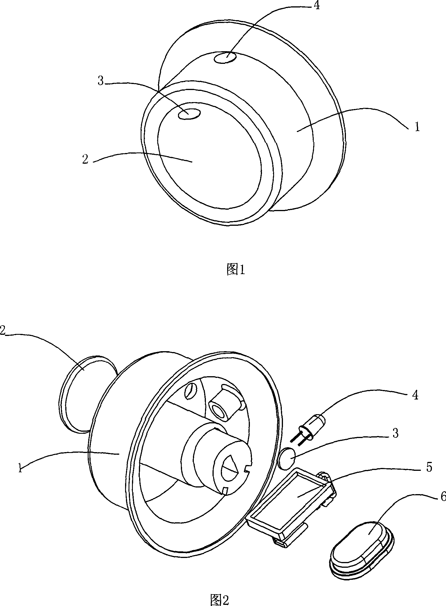
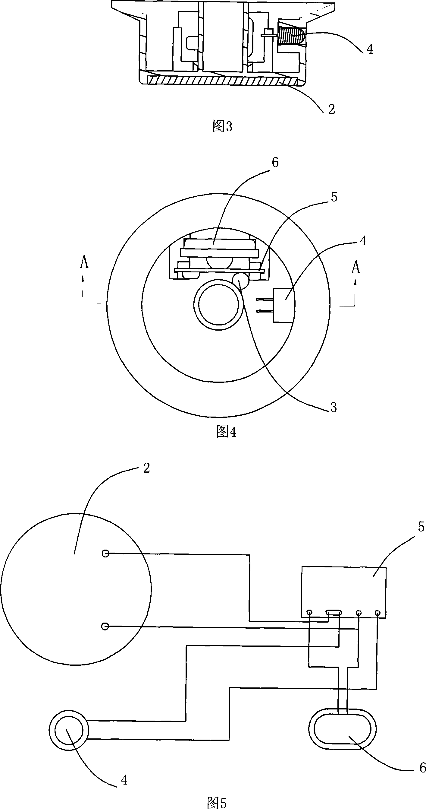
[0026] As shown in FIGS. 1 to 4 , the knob solar lighting mechanism includes a knob 1 , a solar cell 2 , a light control switch 3 , a lighting lamp 4 , a circuit board 5 , and a micro battery 6 .
[0027] As shown in Figures 1 and 2, the knob 1 is cylindrical, and the solar cell 2 is installed on the outer surface of the knob 1; the solar cell 2 can be used as a part of the housing of the knob 1, so that The material used for the knob is saved, and solar energy can be absorbed and accumulated, killing two birds with one stone. The illuminating lamp 4 is installed on the cylindrical surface of the knob 1, and the light control switch 3 is installed on the outer surface of the knob 1, so as to facilitate the light control switch to detect the surrounding light visibility.
[0028] As shown in Fig. 3 and Fig. 4, the battery 6 and the circuit board 5 are installed in the internal space of the cylindrical knob 1, so that the whole knob lighting device has a compact and simple struc...
Embodiment 2
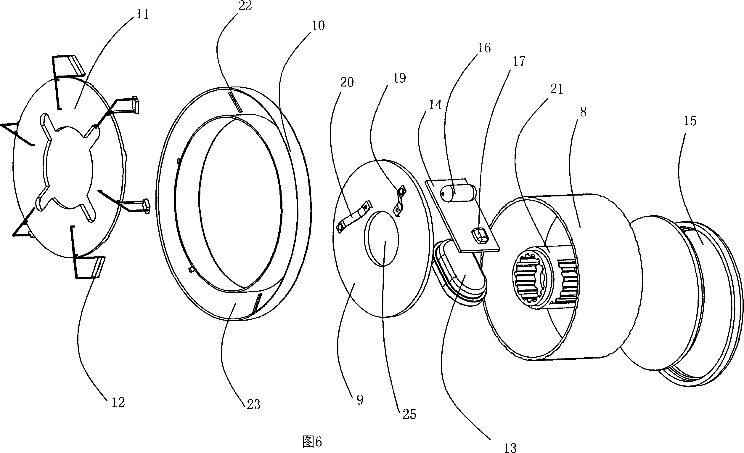
[0031] As shown in FIG. 6 , the knob solar lighting mechanism includes a knob 8 , a solar cell 15 , a circuit board 14 , a light control switch 16 , a manual switch 17 , a storage battery 13 , a knob seat 10 , an electric comb plate 11 and a brush plate 9 .
[0032] Wherein, the knob 8 is barrel-shaped, the solar cells 15 are fixed on its circular outer surface, the circular inner surface of the knob 8 is fixed with a ring-shaped fixing post 21, and the circuit board 14 and the storage battery 13 are installed on the knob 8. In the internal space; the knob 8 is installed on the knob base 10 .
[0033] The knob base 10 is a hollow cylindrical ring with a "U"-shaped longitudinal section. Six scale holes 22 are arranged on the outer surface of the knob base 10. The electric comb plate 11 is installed on the "U" of the knob base 10. Shaped groove 23.
[0034] As shown in Fig. 6, Fig. 7 and Fig. 9, described electric comb plate 11 is circular, and its periphery is corresponding to...
PUM
 Abstract
Description
Claims
Application Information