Special logic control device for nucleus electromotor unit drive

A special logic and technology for nuclear power units, applied in nuclear power plant control, electrical program control, program control in sequence/logic controllers, etc., can solve problems such as unclear interface and poor portability, and achieve simplification of control logic programming work , small mutual influence and high degree of standardization

Active Publication Date: 2008-05-28
CHINA ENERGY ENG GRP GUANGDONG ELECTRIC POWER DESIGN INST CO LTD
View PDF0 Cites 18 Cited by
  • Summary
  • Abstract
  • Description
  • Claims
  • Application Information

AI Technical Summary

Problems solved by technology

[0003] The object of the present invention is to provide a Independent and standardized nuclear power unit drive-level dedicated logic control device

Method used


Image

  • Special logic control device for nucleus electromotor unit drive
  • Special logic control device for nucleus electromotor unit drive
  • Special logic control device for nucleus electromotor unit drive

Examples


specific Embodiment 1

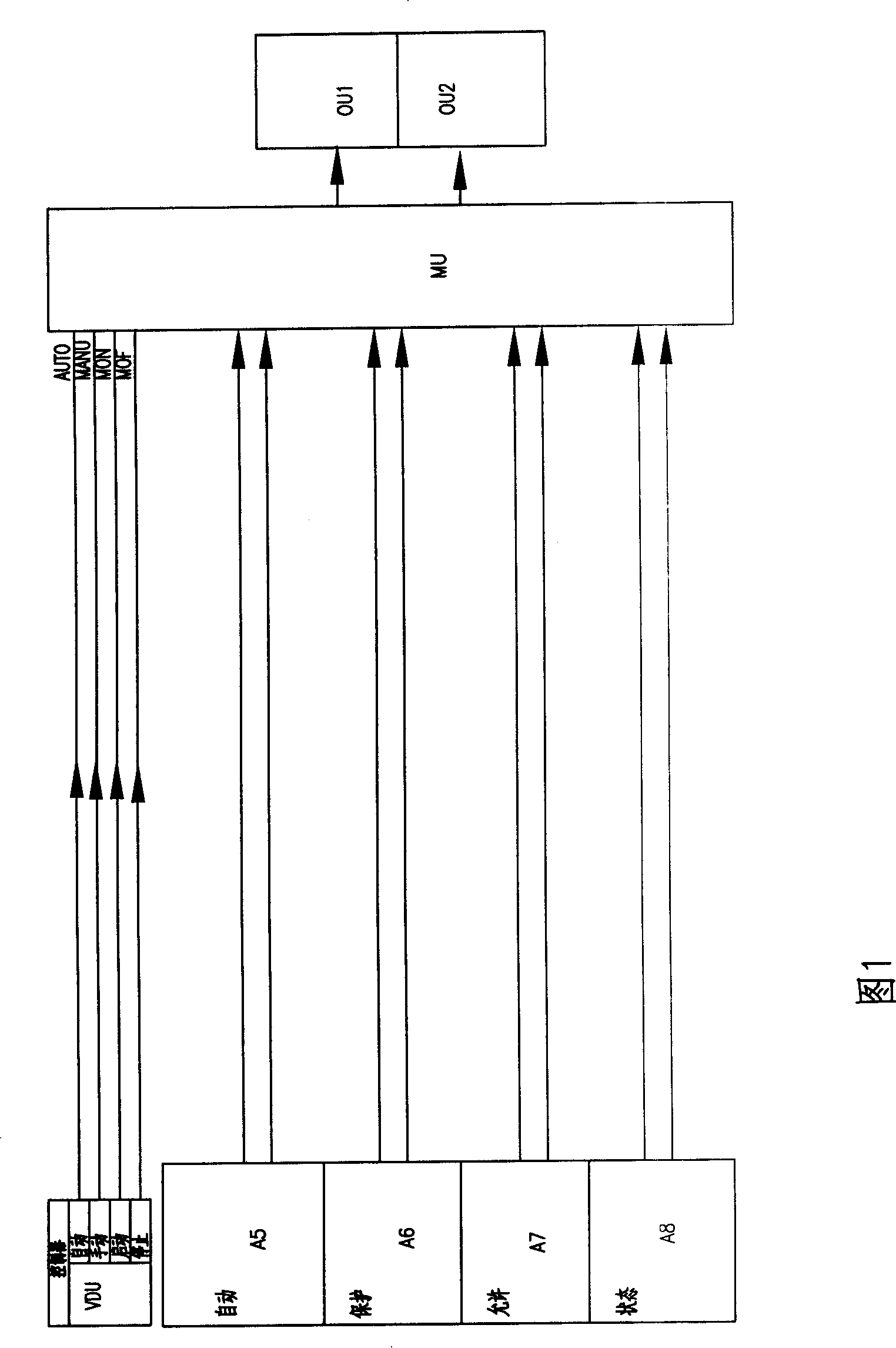
[0022] Fig. 1, Fig. 2 constitute specific embodiment 1 of the present invention. It constitutes a dedicated logic control device for pumps / fans.

[0023] Referring to Fig. 1, the present embodiment consists of logic function module MU, switching controller VDU, automatic signal input port A5, protection signal input port A6, permission signal input port A7, equipment operation status signal input port A8, logic control signal output port OU1 and equipment operation state signal output port OU2; switching controller VDU switching button and control button, a group of signal input terminals of the logic function module MU are connected with the output terminals of the switching controller VDU, switching button and control button; logic function module MU A group of signal input ports of a group are respectively connected with the automatic signal input port A5, the protection signal input port A6, and the allowable signal input port A7, and the signal output port of the logic func...

specific Embodiment 2

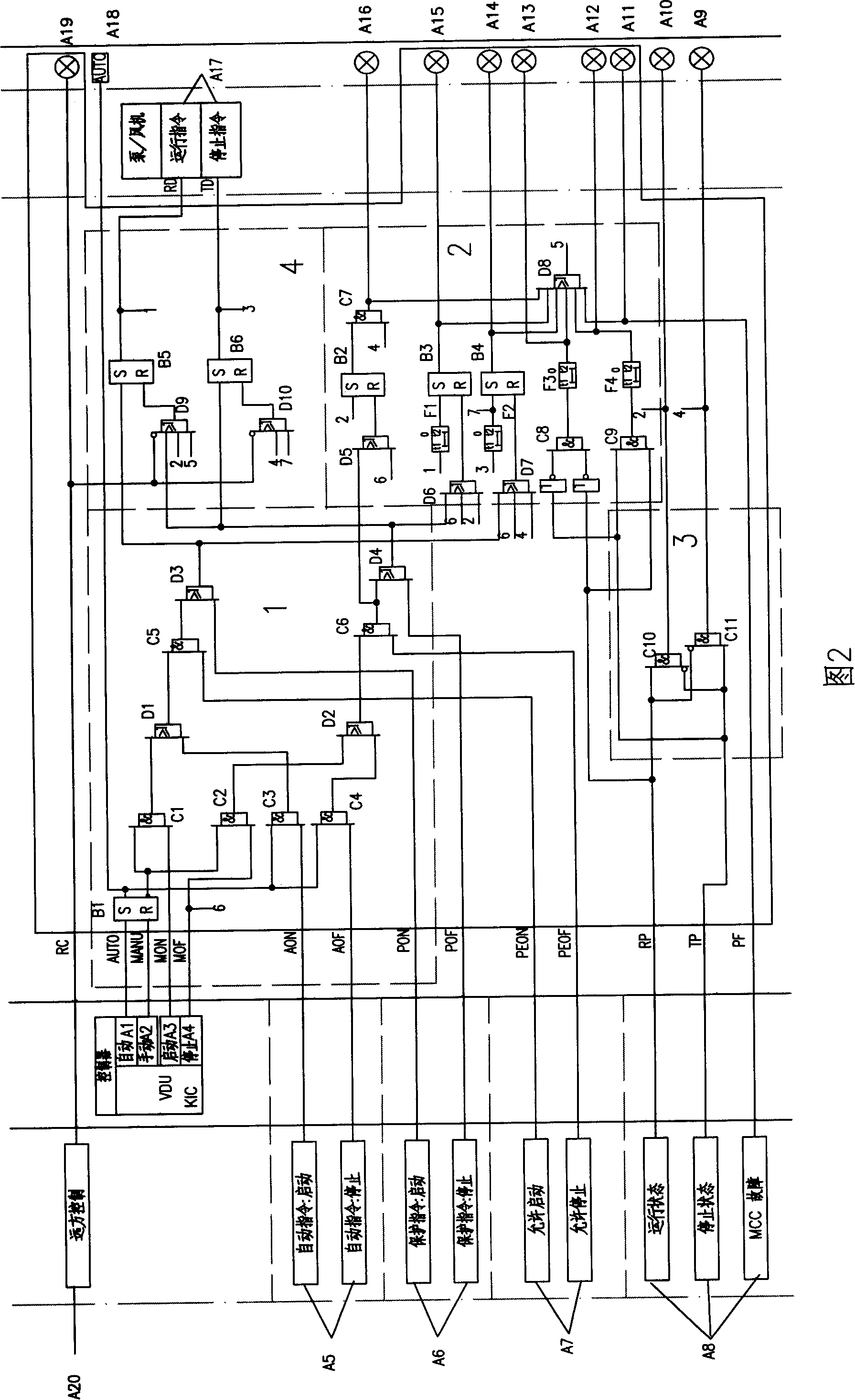
[0044] Figure 1 and Figure 3 constitute Embodiment 2 of the present invention. It constitutes a dedicated logic control device for fully opening or fully closing electric doors / baffles.

[0045] Referring to Fig. 3, the logic function module MU in the present embodiment is made up of input instruction processing logic circuit 1, fault judgment and processing logic circuit 2, state processing logic circuit 3 and output instruction generation logic circuit 4; Wherein:

[0046] The input instruction processing logic circuit includes RS flip-flop B1, AND gates C1-C6, OR gates D1-D5 and NOT gate E1; the S input terminal of RS flip-flop B1 is connected to the automatic button A1, and the R input terminal is connected to the manual button A2 , its inverting output end is connected to an input end of AND gate C1 and C2, its non-inverting output end is connected to AUTO port A18 and an input end of AND gate C3, C4; an input end of AND gate C1, or gate D5 One input terminal is connecte...

specific Embodiment 3

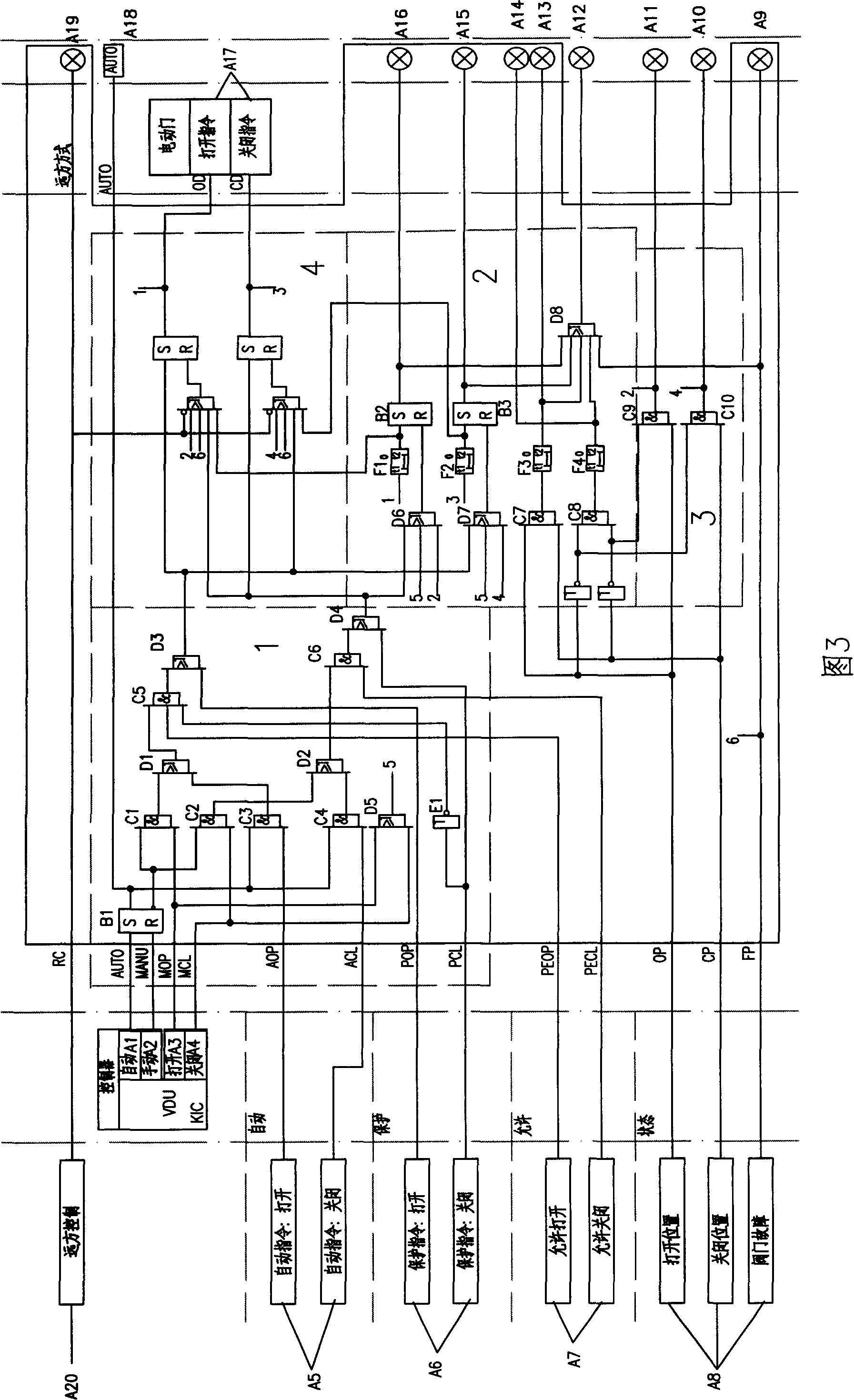
[0050] Fig. 1, Fig. 4 constitute embodiment 3 of the present invention. It constitutes a dedicated logic control device for inching electric doors / baffles.

[0051] Referring to Fig. 4, the logic function module MU in the present embodiment is made up of input instruction processing logic circuit 1, fault judgment and processing logic circuit 2, state processing logic circuit 3 and output instruction generation logic circuit 4; Wherein:

[0052] The input instruction processing logic 1 includes RS flip-flop B1, AND gates C1-C6, OR gates D1-D4 and NOT gate E1; the S input terminal of RS flip-flop B1 is connected to the automatic button A1, and the R input terminal is connected to the manual button A2 , its inverting output terminal is connected to an input terminal of AND gates C1 and C2, its output terminal is connected to AUTO port A16 and an input terminal of AND gate C3, C4; an input terminal of AND gate C1 is connected to the open button A3, One input terminal of AND gate...


PUM


Abstract

The invention relates to a special logic control device with a nuclear power set driving stage, which is characterized in that the invention comprises a logic functional module MU, a switch controller VDU, an automatic signal input port A5, a protection signal input port A6, a permitting signal input port A7, an equipment running state signal input port A8, a logic control signal output port OU1 and an equipment running state signal output port OU2, wherein, the switch controller VDU comprises a switch button and a control button. One group of signal input ends of the logic functional module MU are communicated with output ends of the switch button and the control button of the switch controller VDU. One group of signal input ends of the logic functional module MU are communicated with the signal port, and the signal output end is communicated with the logic control signal output port OU1. The equipment running state signal input port A8 is connected with the state testing end of controlled equipment, and the state signal output end of the logic functional module MU is communicated with the equipment running state signal output port OU2. The invention has the effects of clear interface, simple programmed work, easy modification and expansion and small influence among each other. The invention is widely suitable for the automatic logic control of a rear state driving mechanism of a nuclear power station with a stage of 1000mw.

Description

technical field [0001] The invention relates to a special logic control device for the driving stage of a nuclear power unit, which is suitable for the automatic logic control of the rear-stage driving mechanism of a 1000MW nuclear power plant. It belongs to the technical field of nuclear power plant electrical equipment. Background technique [0002] At present, domestic 1000MW nuclear power units are generally imported from abroad, and their logic control circuits are designed by foreign companies. The automatic logic control device of the circuit is composed of logic elements such as AND gate, OR gate, NOT gate, and memory to realize various logic control functions. However, for the design of the logical control part of the pump / fan, electric valve, pneumatic valve and other post-level drive equipment, only some basic logic elements are set in the overall logic control circuit. These basic logic units adopt decentralized non-standardized The design is not targeted, and ...

Claims


Application Information

Patent Timeline
Patent Type & Authority Applications(China)
IPC IPC(8): G21D3/00G05B19/04G05B19/05
CPCY02E30/40Y02E30/00
Inventor 刘宇穗伍广俭罗颖坚薛沛华李俊
Owner CHINA ENERGY ENG GRP GUANGDONG ELECTRIC POWER DESIGN INST CO LTD
Why Eureka
Try Eureka