A dual-frequency mixed spectrum type and pulse width regulation type dimming electronic ballast

A technology of pulse width adjustment and light mixing, which is applied in the direction of light source, electric light source, electrical components, etc., can solve the problems of dual-frequency mixed light pulse width adjustment, etc., and achieve easy harmonic control and improve cost performance Effect

CN101217848AInactive Publication Date: 2008-07-09李东方 +2
3 Cites 3 Cited by

Patent Information

Authority / Receiving Office
CN · China
Patent Type
Applications(China)
Current Assignee / Owner
Publication Date
2008-07-09
Estimated Expiration
Not applicable · inactive patent

Smart Images

  • Figure 1
    Figure 1
  • Figure 2
    Figure 2
  • Figure 3
    Figure 3
Patent Text Reader

Abstract

The invention provides a dual-frequency lighting mixed pulse width modulation dimming electronic ballast, relating to an electronic ballast. The invention provides a dual-frequency lighting mixed pulse width modulation dimming electronic ballast which can ensure the lightness of the lamp to be in 100% to 30% with reliable light modulation, leads to no flashing lamp phenomenon, is convenient for being applied in single-line illumination control circuits and can be widely applied to existing energy-saving lamps and ballasts. The invention is provides with a rectification circuit, a zero cross detection circuit, a system control circuit, a dual-frequency point power output circuit and a lamp driving circuit. The input terminal of the rectification circuit is externally connected with a power supply; the input terminal of the zero cross detection circuit is connected with the output terminal of the rectification circuit; the input terminal of the system control circuit is connected with the output terminal of the zero cross detection circuit; the power supply input terminal of the dual-frequency point power output circuit is connected with the output terminal of the rectification circuit; the control input terminal of the dual-frequency point power output circuit is connected with the system control circuit; the input terminal of the lamp driving circuit is connected with the output terminal of the dual-frequency point power output circuit; the output terminal of the lamp driving circuit is externally connected with loads.
Need to check novelty before this filing date? Find Prior Art

Description

technical field

[0001] The invention relates to an electronic ballast, in particular to a dual-frequency mixed-light pulse-width adjustable dimming electronic ballast mainly used for compact energy-saving lamps or electronic ballasts. The invention can be directly applied to the ordinary two-wire series lighting control circuit, and can realize the dimming function of the energy-saving lamp or the fluorescent lamp without modifying the original switch lighting circuit. Background technique

[0002] Existing energy-saving lamps cannot be dimmed, and energy-saving lamps cannot be added to professional dimming systems. Some electronic ballasts with dimming interfaces cannot be widely used due to their high cost and the need for dedicated line control.

[0003] The Chinese invention patent application with the publication number CN1407840 provides a phase-controlled dimmable electronic ballast for fluorescent lamps with an extremely wide dimming range. In order to obtain a wide ...

Examples

Embodiment Construction

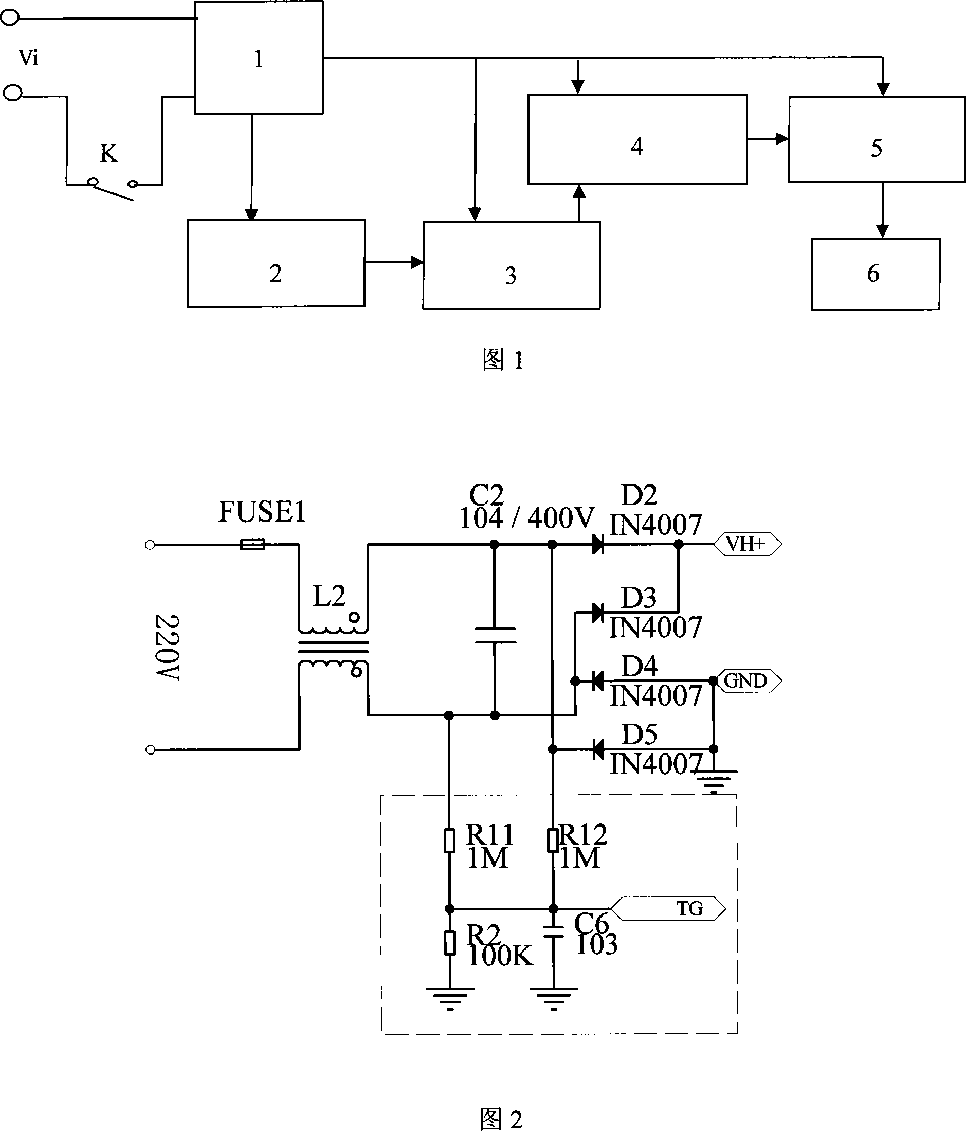
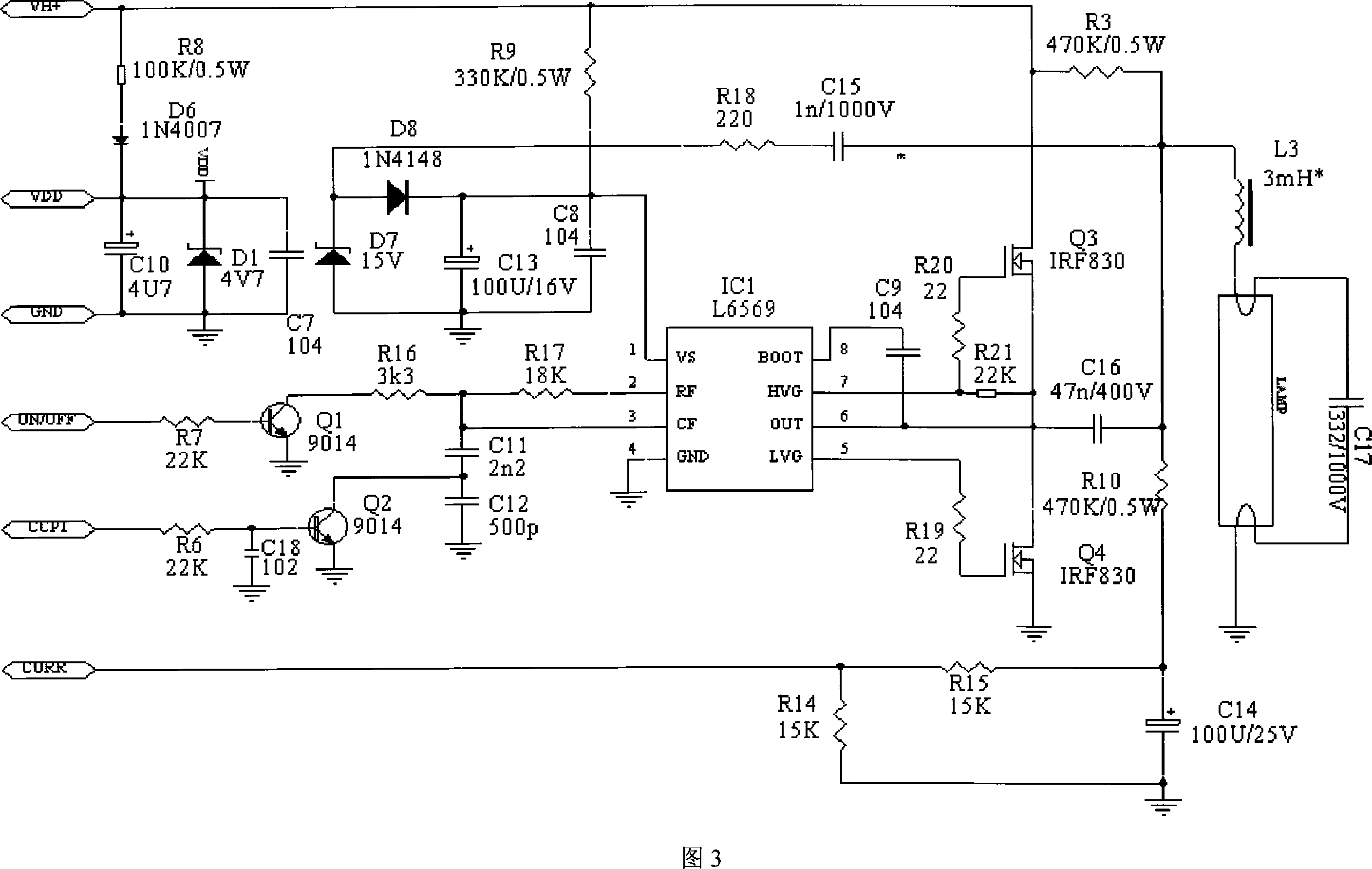
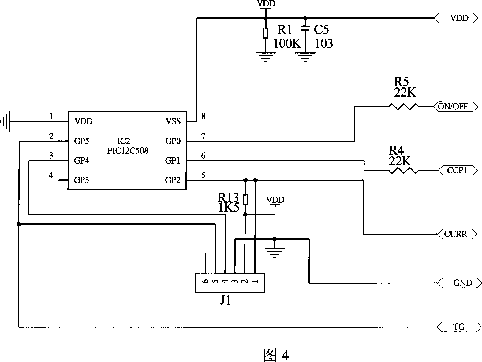
[0029] Referring to FIG. 1 , the present invention is provided with a rectification circuit 1 , a zero-crossing detection circuit 2 , a system control circuit 3 , a dual-frequency point power output circuit 4 and a lamp driving circuit 5 . The rectification circuit 1 is used to convert the AC power Vi into a DC power supply for other circuits, and the input end of the rectification circuit 1 is externally connected to the AC power Vi for power supply. The zero-crossing detection circuit 2 is used to shape the on-off of the AC side power supply or the change of the power waveform and then transmit it to the microprocessor in the system control circuit 3 for processing. The input terminal of the zero-crossing detection circuit 2 is connected to the output terminal of the rectification circuit 1 . The system control circuit 3 is used to control the frequency change of the variable frequency power output by synchronizing the on-off control signal from the power supply to the power ...