
Multiple light-source driver, light-crystal displaying device and driving method thereof

A technology of a liquid crystal display and a driving method, which is applied in the field of multi-light source drivers, can solve the problems such as the decrease of the brightness of the picture, the large change of the brightness of the display picture, and the influence on the quality of the display picture, and the effect of avoiding the blurring of the picture is achieved.

Inactive Publication Date: 2007-04-11
GIGNO TECH CO LTD
View PDF4 Cites 0 Cited by
  • Summary
  • Abstract
  • Description
  • Claims
  • Application Information

AI Technical Summary

Problems solved by technology

However, as far as this kind of flash technology is concerned, because it continuously turns on and off the light-emitting unit, the brightness of the display screen varies greatly, and this phenomenon will therefore lead to visual flicker (flicker) phenomenon.
Furthermore, constantly turning on and off the light-emitting unit will also reduce the overall brightness of the screen, thereby affecting the quality of the display screen.
In addition, when the light-emitting unit is turned off and on again, the current change of the lamp as the light-emitting unit will go through a transient response interval (transient), and it will be difficult to accurately control the current and brightness of the lamp within this interval. It is also difficult to ensure the uniformity of brightness among the light-emitting units

Method used


Image

  • Multiple light-source driver, light-crystal displaying device and driving method thereof
  • Multiple light-source driver, light-crystal displaying device and driving method thereof
  • Multiple light-source driver, light-crystal displaying device and driving method thereof

Examples


Embodiment Construction

[0043] A preferred embodiment of the liquid crystal display driving method according to the present invention will be described below with reference to related drawings. It should be noted here that, in this embodiment, the liquid crystal display includes a backlight module, a display panel, and a multi-light source driver (device), the backlight module has a plurality of light emitting units, and each light emitting unit includes at least One light tube, that is, each light-emitting unit can contain more than two light tubes. Instead, the lamp can be a cold cathode fluorescent lamp (CCFL). The display panel has a plurality of scan lines. In addition, in this embodiment, the liquid crystal display is a TFT-LCD, and its backlight is a direct back-light unit.

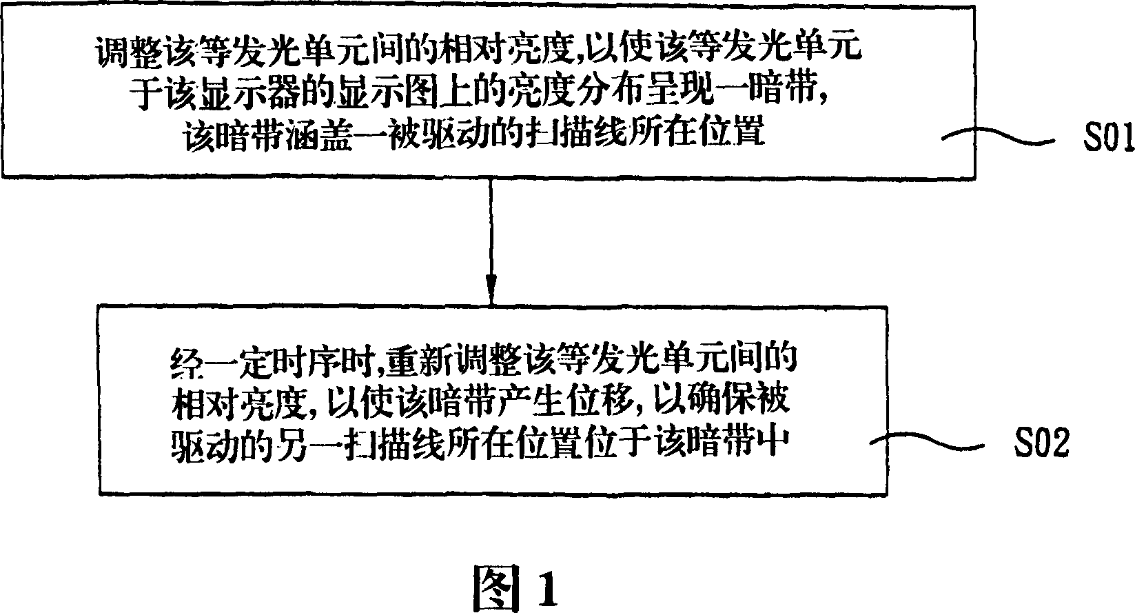
[0044]As shown in FIG. 1 , the liquid crystal display driving method includes a first brightness adjustment step S01 and a second brightness adjustment step S02 .

[0045] In the first brightness adjustment step S01, a...


PUM


Abstract

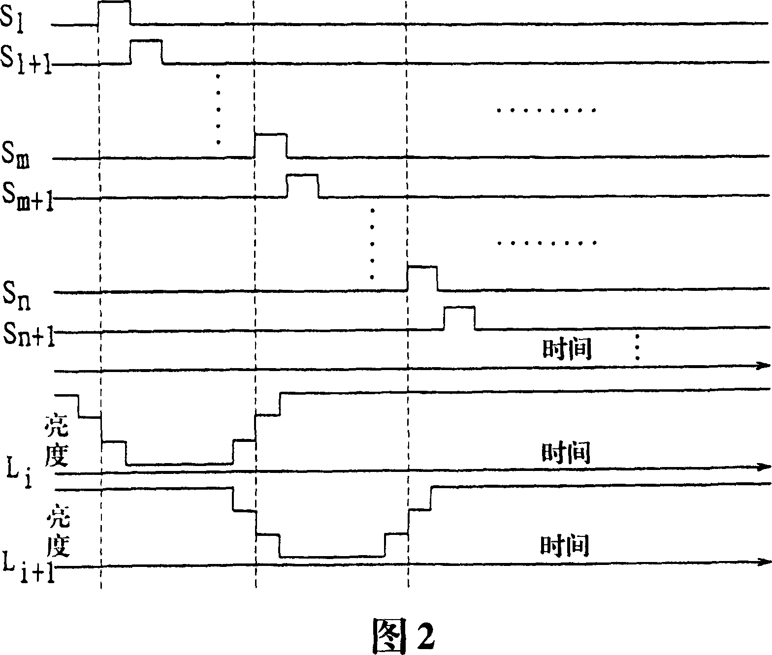
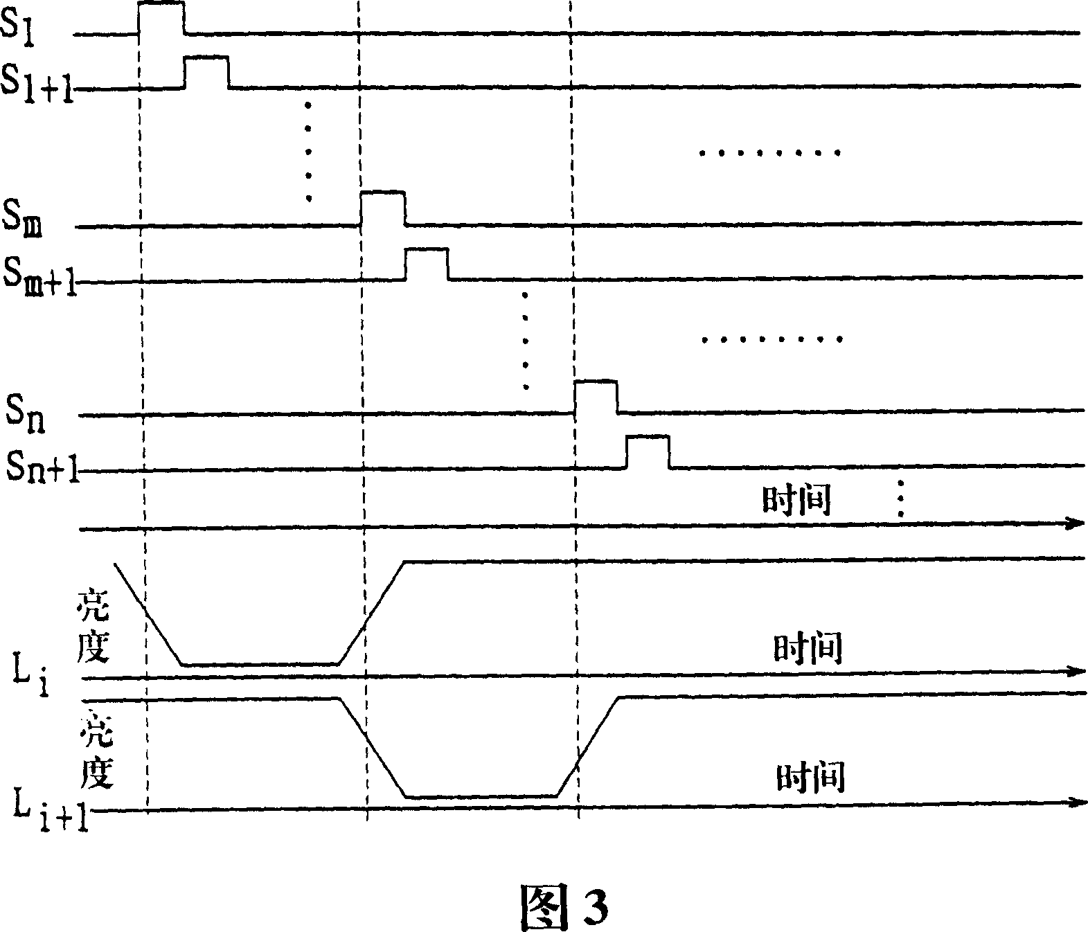
A method for driving a liquid crystal display comprises the first luminance adjusting procedure and the second luminance adjusting procedure. In the first luminance adjusting procedure, the relative luminance between a plurality of lighting units is adjusted to make the luminance distribution of the equal lighting units on the displayed tableau on the displaying panel of the liquid crystal display assume a dark zone which covers the position of a driven scanning line; in the second luminance adjusting procedure, the relative luminance between the equal lighting units is adjusted again in a certain sequence to make the position of the dark zone change to ensure that another driven scanning line is positioned in the dark zone. Furthermore, the invention also provides a liquid crystal display and a driver of complex light sources.

Description

technical field [0001] The present invention relates to a multi-light source driver, a liquid crystal display and a driving method thereof, in particular to a multi-light source driver, a liquid crystal display and a driving method thereof capable of generating a sequentially moving dark zone on a display screen of a liquid crystal display. method. Background technique [0002] At present, liquid crystal displays (hereinafter referred to as LCD) are widely used in electronic products such as computers, and with the development of LCD technology, the display quality of LCD is getting higher and higher and its size is also increasing. As a display screen for a TV. However, since most of the images played on TV are moving picture images, when an LCD is selected as the display screen, the image display method of the LCD often causes a phenomenon of persistence of vision, resulting in image blurring. )And other issues. This problem limits the application of LCD in TV display, ...

Claims


Application Information

Patent Timeline
Patent Type & Authority Patents(China)
IPC IPC(8): G09G3/36G09G5/10
Inventor 赵元任
Owner GIGNO TECH CO LTD
Learn More