Coil body for an electric coil and method for producing an electronic element provided with said coil body

A technology of electronic components and bobbins, applied in the direction of transformer/inductor coil/winding/connection, transformer/inductor parts, coils, etc., can solve problems such as troublesome and extra costs, and achieve trouble-free manufacturing process and cheap manufacturing , reliable and safe insulation effect

Inactive Publication Date: 2008-07-30
PATENT TREUHAND GESELLSCHAFT FUR ELECTRIC GLUEHLAMPEN MBH
View PDF0 Cites 0 Cited by
  • Summary
  • Abstract
  • Description
  • Claims
  • Application Information

AI Technical Summary

Problems solved by technology

But this would result in significant additional costs and a much more complex implementation

Method used


Image

  • Coil body for an electric coil and method for producing an electronic element provided with said coil body
  • Coil body for an electric coil and method for producing an electronic element provided with said coil body
  • Coil body for an electric coil and method for producing an electronic element provided with said coil body

Examples


Embodiment Construction

[0025] In the figures, identical or functionally identical elements are provided with the same reference signs.

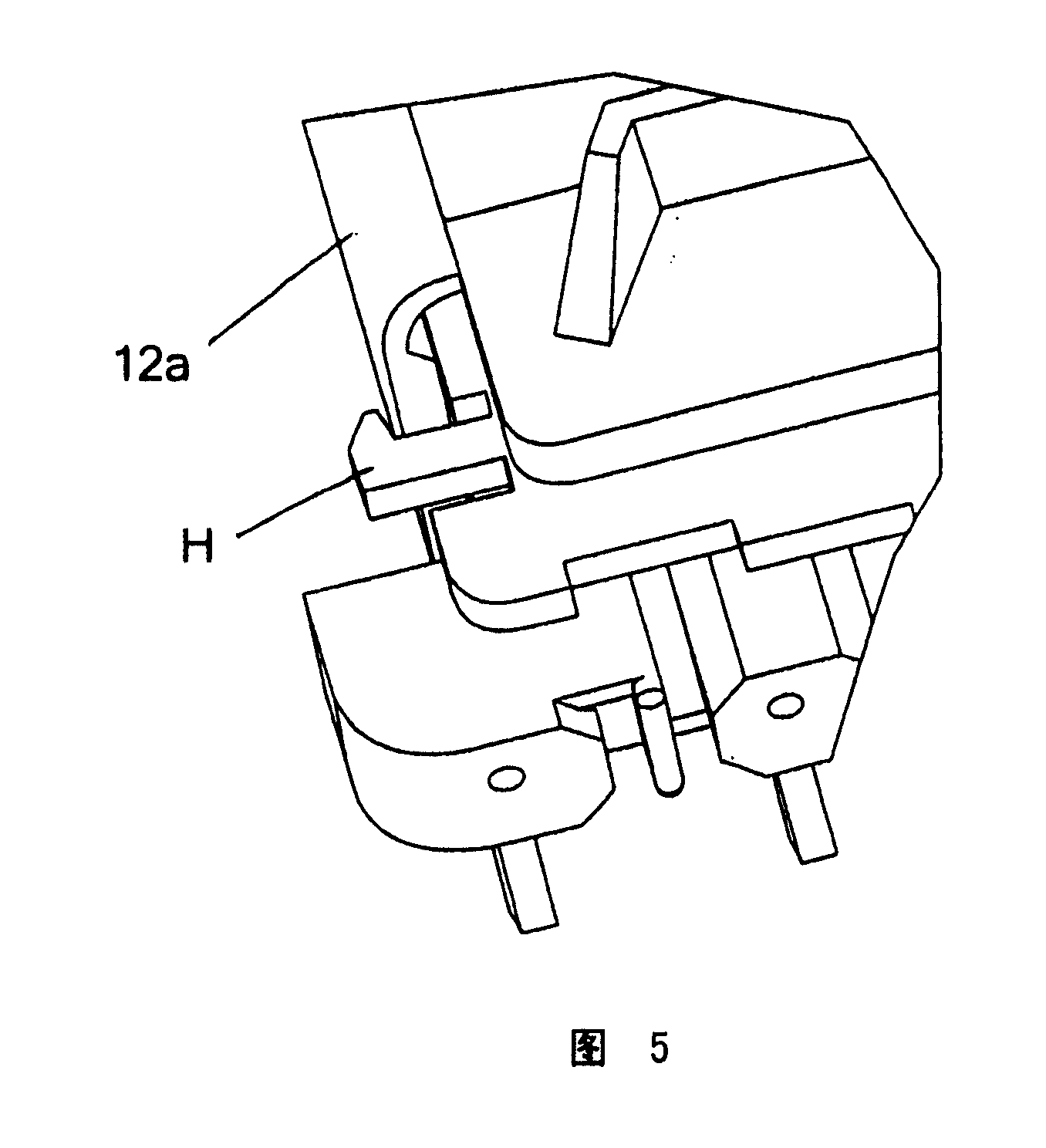
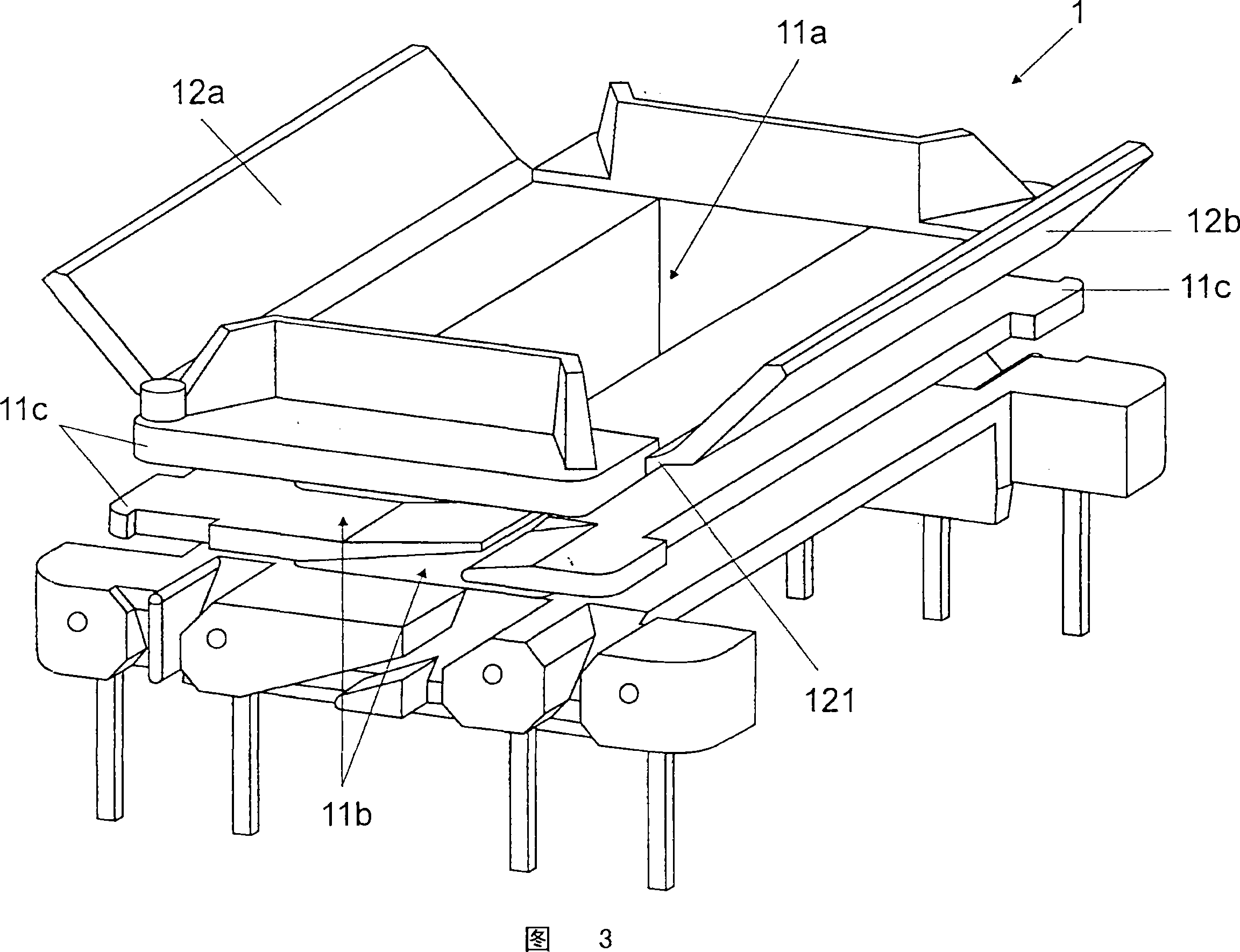
[0026] The coil former 1 according to the invention is shown in the schematic diagram of FIG. 3 . Said coil former 1, in its essential element for the invention, comprises an intermediate region with a hollow interior 11a. A partial area of ​​the coil core 2 (not shown) can be positioned in this hollow lumen 11a. The middle region has an outer side 11b on which the winding 3 (not shown) can be wound completely around the middle region of the coil former 1 . As can be seen, the stationary positioning element 11c rests on this outer side surface 11b. As a result, the position of the winding 3 arranged on the outer side 11b can be kept stable. The movable flaps 12a and 12b are mounted on the coil former 1 as the main elements of the coil former 1 according to the invention. As can be seen, in the embodiment according to FIG. 3 the two flaps 12a and 12b are arrange...


PUM


Abstract

The invention relates to a bobbin for an electronic coil having a hollow central region for receiving a partial region of a coil core (2) in an interior space (11a) of the hollow central region and for accommodating at least one winding (3) Winding on the outer side (11b) of the middle area, wherein the movable flip (12a, 12b) is arranged on the side area of ​​the coil former (1), the movable flip (12a, 12b) is constructed such that the movable flip In the closed state, electrical insulation is formed between the winding (3) and adjacently arranged outer legs (21) of the coil core (2). The invention also relates to an electronic component having such a coil former (1) and to a method for producing such an electronic component.

Description

technical field [0001] The invention relates to a coil former for an electrical coil, wherein the coil former has a hollow central region for accommodating a partial region of the coil core, and on the outer side of which the winding can be wound. Furthermore, the invention also relates to an electronic assembly comprising such a coil former. In addition to this, the invention also relates to a method for producing an electronic assembly with such a coil former. Background technique [0002] A magnetic assembly known from the prior art is schematically represented in FIG. 1 . The assembly has a coil former 1 which is at least partially surrounded by a coil core 2 . The coil former 1 also comprises a hollow central region, which is not discernible in the illustration according to FIG. 1 , for receiving a partial region of the coil core 2 . The coil core 2 is usually composed of ferrite. As can be discerned, the winding 3 , eg, made of copper wire, can be wound on the oute...

Claims


Application Information

Patent Timeline
Patent Type & Authority Applications(China)
IPC IPC(8): H01F5/02H01F27/32H01F5/06
CPCY10T29/49073H01F5/02H01F2005/043H01F27/325H01F2005/022H01F27/32
Inventor W·埃伯特J·克利尔B·奥尔本
Owner PATENT TREUHAND GESELLSCHAFT FUR ELECTRIC GLUEHLAMPEN MBH
Why Eureka
Try Eureka