

Turbine with variable inlet nozzle geometry
A technology for turbines and turbine impellers, applied in the field of turbochargers and variable turbochargers, which can solve problems such as difficult guarantees and increased nozzle ring loads
- Summary
- Abstract
- Description
- Claims
- Application Information
AI Technical Summary
Problems solved by technology
Method used
Image

Examples
Embodiment Construction
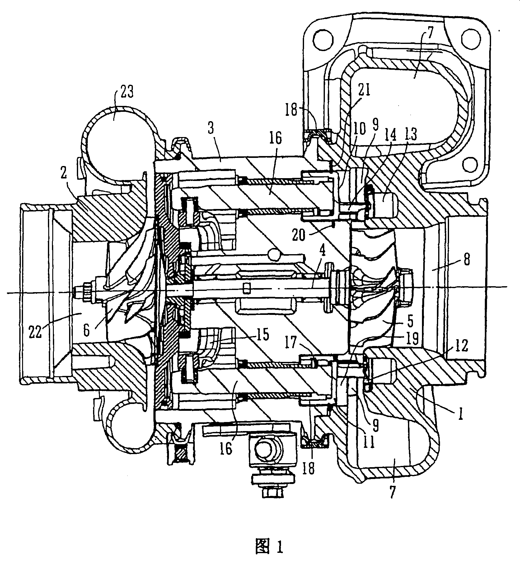
[0065] refer to figure 1 , the variable turbocharger shown includes a variable turbine housing 1 and a compressor housing 2 connected to each other through a central bearing housing 3 . A turbocharger shaft 4 extends from the turbine housing 1 to the compressor housing 2 through the bearing housing 3 . The turbine wheel 5 is mounted on one end of the shaft 4 for rotation in the turbine housing 1 and the compressor wheel 6 is mounted on the other end of the shaft 4 for rotation in the compressor housing 2 . The shaft 4 rotates about a turbocharger axis 4a on a bearing assembly in a bearing housing.
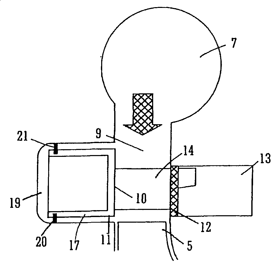
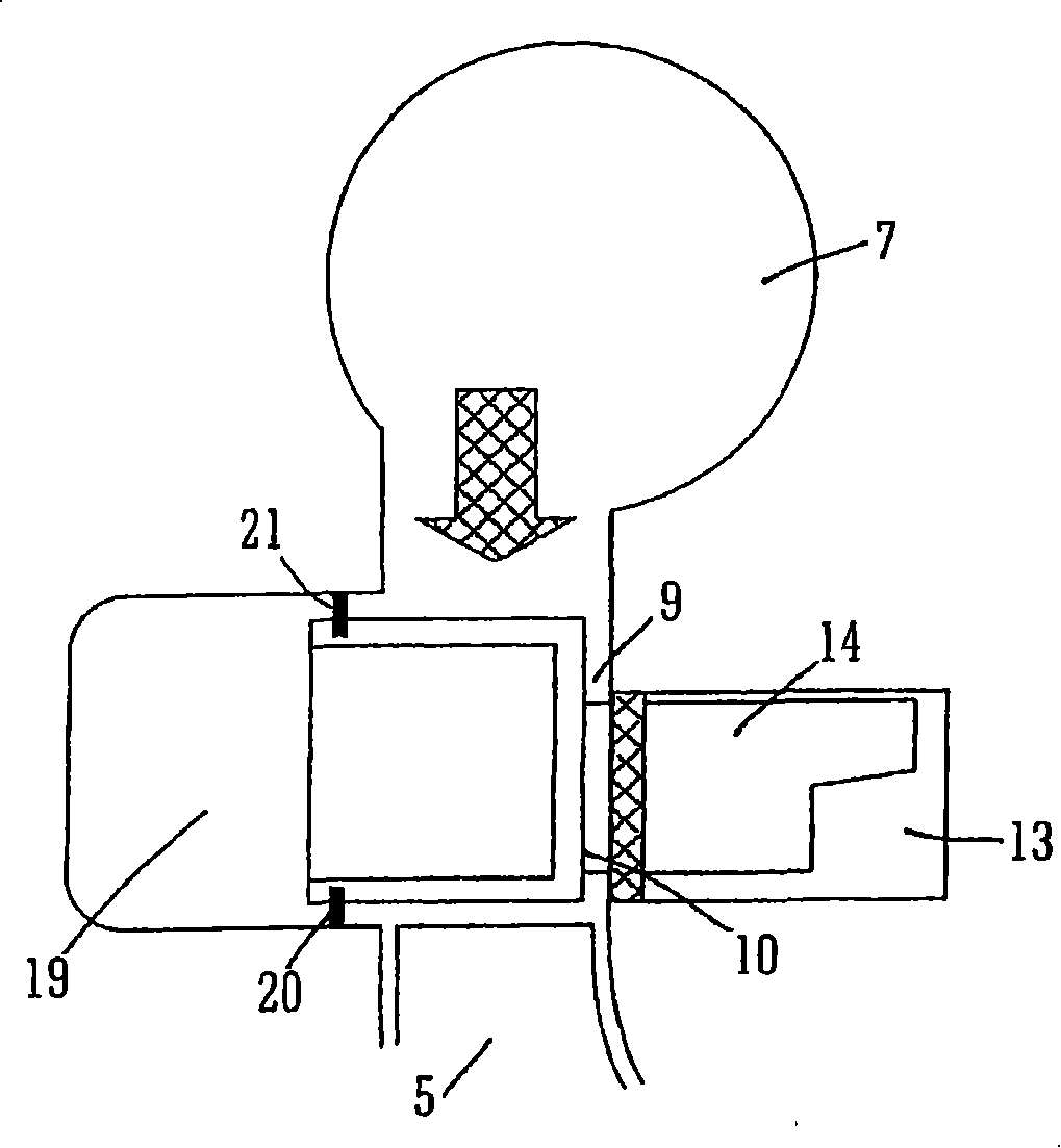
[0066] The turbine housing 1 defines an intake chamber 7 (typically scroll-shaped) into which gas is delivered from an internal combustion engine (not shown). Exhaust gas flows from the inlet chamber 7 to the axial outlet channel 8 via the annular inlet channel 9 and the turbine wheel 5 . The inlet channel 9 is delimited on one side by a radial wall surface 10 of a movable annul...
PUM
 Abstract
Description
Claims
Application Information