Zigzag slow-wave line of double ridged waveguide

A technology of double ridge waveguide and meander line, applied in the field of traveling wave tube amplifier

Inactive Publication Date: 2009-11-04
UNIV OF ELECTRONICS SCI & TECH OF CHINA
View PDF0 Cites 31 Cited by
  • Summary
  • Abstract
  • Description
  • Claims
  • Application Information

AI Technical Summary

Problems solved by technology

[0005] In order to further improve the bandwidth performance and expand the working frequency band; at the same time, in order to more effectively utilize the magnetic field resources of the focusing system and solve the magnetic field focusing problem caused by the small electron beam radius, the present invention proposes a meandering double-ridge waveguide slow wave line

Method used


Image

  • Zigzag slow-wave line of double ridged waveguide
  • Zigzag slow-wave line of double ridged waveguide
  • Zigzag slow-wave line of double ridged waveguide

Examples


Embodiment Construction

[0019] specific implementation plan

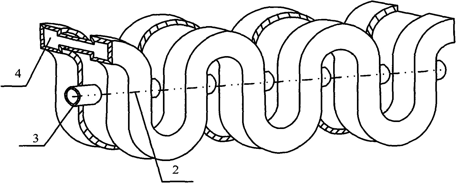
[0020] Such as Figure 4 , in the 8mm millimeter wave band, the structural dimensions of the specific scheme of the meandering double-ridge waveguide slow wave line are as follows (unit: mm):

[0021] a=5, b=1, L=4.76, p=1.5, r 0 = 0.5, a 0 =2.5,b 0 = 0.4. Use the 3D electromagnetic simulation software to simulate the meandering double-ridge waveguide slow wave line to obtain its dispersion characteristics, and compare it with the dispersion characteristics of the ordinary meandering waveguide slow wave line. The simulation results are as follows Figure 5 shown. Curve 5 is the dispersion characteristic of the meandering double-ridge waveguide slow-wave structure, and curve 6 is the dispersion characteristic of the ordinary meandering waveguide slow-wave structure.

[0022] From Figure 5 From the comparison between curve 5 and curve 6, it can be clearly seen that the meandering double-ridge waveguide slow-wave line has a lower cut-...


PUM


Abstract

A zigzag slow-wave line of double ridged waveguide belongs to the technical field of microwave vacuum electron and relates to a traveling-wave tube amplifier. A slow-wave structure is formed by periodically bending the double ridged waveguide (4) along the electric field to form a right-angled zigzag line or a U-shaped zigzag line; circular through holes are arranged at the positions along the mean axis symmetric line (2) of the slow-wave structure on the waveguide wall; and the slow-wave lines are connected by the metal tubes (3) with the aperture the same with that of the circular through holes between two circular through holes of the right-angled groove or U-shaped groove in each zigzag periodic structure of the slow-wave structure to form an electron stream channel. Compared with conventional zigzag slow-wave line of waveguide, the slow-wave line has lower cut-off frequency, wider pass band range and flatter dispersion characteristics. In addition, in the event that the dispersion characteristics are approximate, the zigzag slow-wave line of double ridged waveguide has smaller cross-sectional dimension to well ensure the transfer characteristics of electron stream in traveling wave tube under the action of the same focusing magnetic field, so as to improve the integral output power and grain of the traveling wave tube.

Description

technical field [0001] The invention belongs to the technical field of microwave vacuum electronics, and relates to a traveling wave tube amplifier. Background technique [0002] Modern traveling wave tubes have become important microwave electronic devices for electronic equipment such as radar, electronic countermeasures, satellite communications, navigation, and remote sensing. The slow wave line is the core of the traveling wave tube, which is the part of the traveling wave tube where the beam-wave interaction excites the microwave energy. Its performance directly determines the technical level of the traveling wave tube. In traveling wave tubes, the most widely used slow wave structures are helix and coupled cavity. The dispersion characteristics of the helix are flat and the working frequency is wide, so it has been widely used in traveling wave tubes; but the output power of the helical traveling wave tube is limited, especially when the traveling wave tube works in ...

Claims


Application Information

Patent Timeline
Patent Type & Authority Applications(China)
IPC IPC(8): H01J23/24
Inventor 魏彦玉何俊王文祥宫玉彬赵国庆
Owner UNIV OF ELECTRONICS SCI & TECH OF CHINA
Why Eureka
Try Eureka