

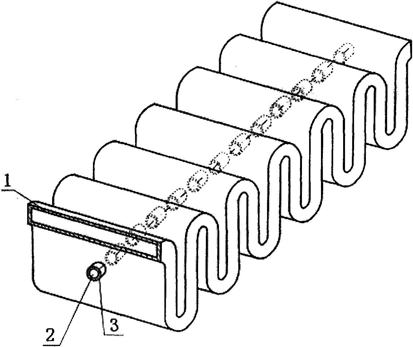
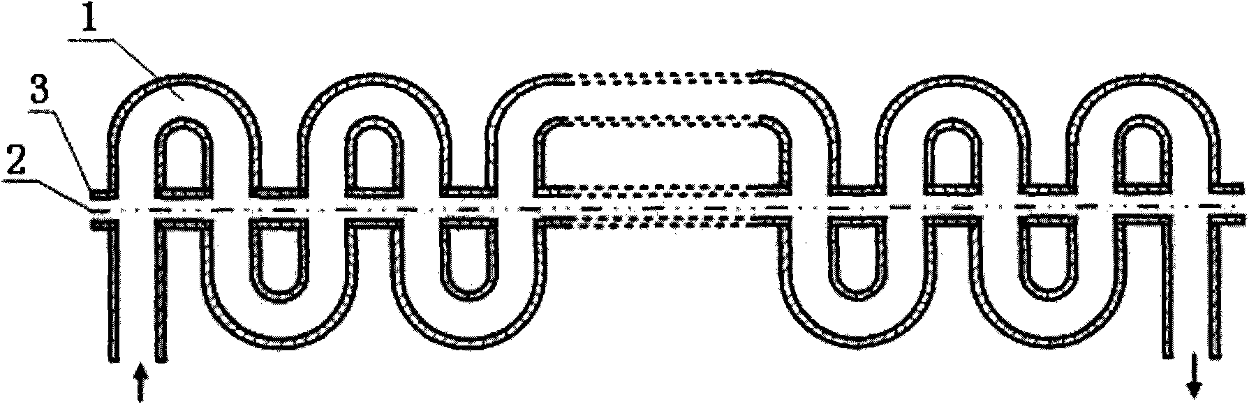
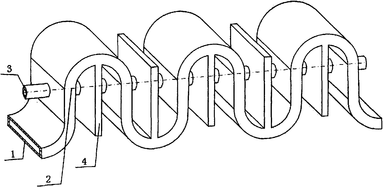
Rectangular-grooved loading winding waveguide slow wave line
A technology of zigzag waveguide and rectangular waveguide, applied in the field of microwave vacuum electronics, can solve the problems of small coupling impedance, limiting output power and gain of traveling wave tube, and low gain, etc.
- Summary
- Abstract
- Description
- Claims
- Application Information
AI Technical Summary
Problems solved by technology
Method used
Image

Examples
Embodiment Construction
[0026] specific implementation plan
[0027] Such as Figure 5 , in the 8mm millimeter wave band, the structural dimensions of the specific embodiment of the rectangular slot loaded meander waveguide slow wave line are (unit: mm): a=5.1, b=0.5, L=3.24, p=1.3, r 0 =0.5,b 0 = 0.2, h 0 =2.44. Use 3D electromagnetic simulation software and 3D beam-wave interaction simulation software to simulate the slow wave line of rectangular slot loaded meander waveguide, obtain its coupling impedance, output power, bandwidth, device length required for power saturation, etc., and compare with ordinary The meander waveguide is compared to the slow wave line. The rectangular slot-loaded meander waveguide slow-wave line has higher coupling impedance, and can output more than twice the power of the ordinary meander-wave waveguide slow-wave line with a smaller volume, and its power will continue to increase at the high end of the working frequency band. The problem of gain drop at the high en...
PUM
 Abstract
Description
Claims
Application Information