Magnetic isolation drive circuit

A drive circuit and isolation drive technology, applied in the direction of electrical components, output power conversion devices, etc., can solve problems such as power failure, power circuit main switch tube malfunction, wrong level signal, etc.

Inactive Publication Date: 2010-01-06
BEIJING SUPLET +1
View PDF0 Cites 16 Cited by
  • Summary
  • Abstract
  • Description
  • Claims
  • Application Information

AI Technical Summary

Problems solved by technology

Therefore, after the pulse width signal disappears, the magnetically isolated drive circuit will generate a wrong level signal, which will cause the main switching tube of the power circuit to malfunction, and may cause the power supply to fail.

Method used


Image

  • Magnetic isolation drive circuit
  • Magnetic isolation drive circuit
  • Magnetic isolation drive circuit

Examples


Embodiment Construction

[0023] In order to clearly illustrate the solutions in the present invention, preferred embodiments are given below and detailed descriptions are given in conjunction with the accompanying drawings.

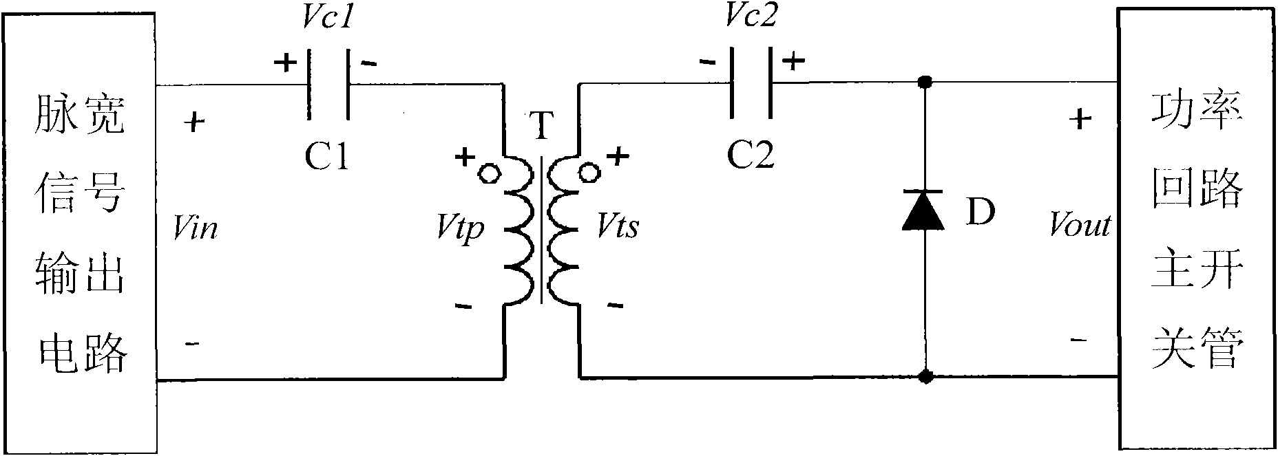
[0024] exist Figure 5 In an optional example shown, the magnetic isolation drive circuit includes: an isolation drive transformer T for transmitting isolated drive signals, a first capacitor C1 connected in series with the input side of the isolation drive transformer, and a first capacitor C1 connected in series with the output side of the isolation drive transformer. The second capacitor C2, the discharge MOS transistor Q connected in parallel with the output terminal of the magnetic isolation drive circuit, and the discharge MOS transistor drive circuit connected to the gate of the discharge MOS transistor Q. Wherein, the output side winding of the isolation drive transformer, the first capacitor C1 and the discharge MOS tube form a series circuit.

[0025] Figure 5 The ma...


PUM


Abstract

The invention discloses a magnetic isolation drive circuit comprising an isolation drive transformer, a first capacitor C1, a second capacitor C2, a discharge MOS pipe and a discharge MOS pipe drive circuit, wherein the isolation drive transformer is used for transmitting an isolation drive signal; the first capacitor C1 is connected with the input side of the isolation drive transformer in series; the second capacitor C2 is connected with the output side of the isolation drive transformer in series; the discharge MOS pipe is connected with the output end of the magnetic isolation drive circuit in parallel; the discharge MOS pipe drive circuit is connected to a grid electrode of the discharge MOS pipe; and a series loop is formed by an output side winding of the isolation drive transformer, the second capacitor C2 and the discharge MOS pipe. The magnetic isolation drive circuit has simple structure and low cost and can effectively increase the stability of a power supply which works in a stable state and a transient state.

Description

technical field [0001] The invention relates to the technical field of drive circuits, in particular to an improved magnetic isolation drive circuit. Background technique [0002] The magnetic isolation driving circuit is widely used in the power supply with high working voltage to drive the main switching tube of the power circuit to turn on and off. figure 1 It is a magnetic isolation drive circuit that we often see. The first capacitor C1 is the input side drive capacitor, the second capacitor C2 is the output side drive capacitor, the transformer T is the isolation drive transformer, and the diode D is connected in parallel with the output terminal of the magnetic isolation drive circuit. figure 1 The principle voltage waveform of each point when the circuit shown is in steady state and normal operation is shown in figure 2 (Ignore the influence of the leakage inductance of the isolation drive transformer T). Among them, Vin is the voltage waveform of the pulse width...

Claims


Application Information

Patent Timeline
Patent Type & Authority Applications(China)
IPC IPC(8): H02M1/08
Inventor 刘红瑞郭霄飞
Owner BEIJING SUPLET
Why Eureka
Try Eureka