Fuel nozzle with device for extracting fuel steams

A technology of fuel vapor and refueling guns, which is applied in distribution devices, special distribution devices, liquid distribution, transportation or transfer devices, etc., and can solve problems such as fuel flow and changes that are not considered

Active Publication Date: 2010-03-24
ELAFLEX GUMMI EHLERS
View PDF1 Cites 5 Cited by
  • Summary
  • Abstract
  • Description
  • Claims
  • Application Information

AI Technical Summary

Problems solved by technology

[0004] In known refueling guns, there is a drawback that the gas valve is fully opened during the refueling process without taking into account possible variations in fuel flow at any particular time

Method used


Image

  • Fuel nozzle with device for extracting fuel steams
  • Fuel nozzle with device for extracting fuel steams
  • Fuel nozzle with device for extracting fuel steams

Examples


Embodiment Construction

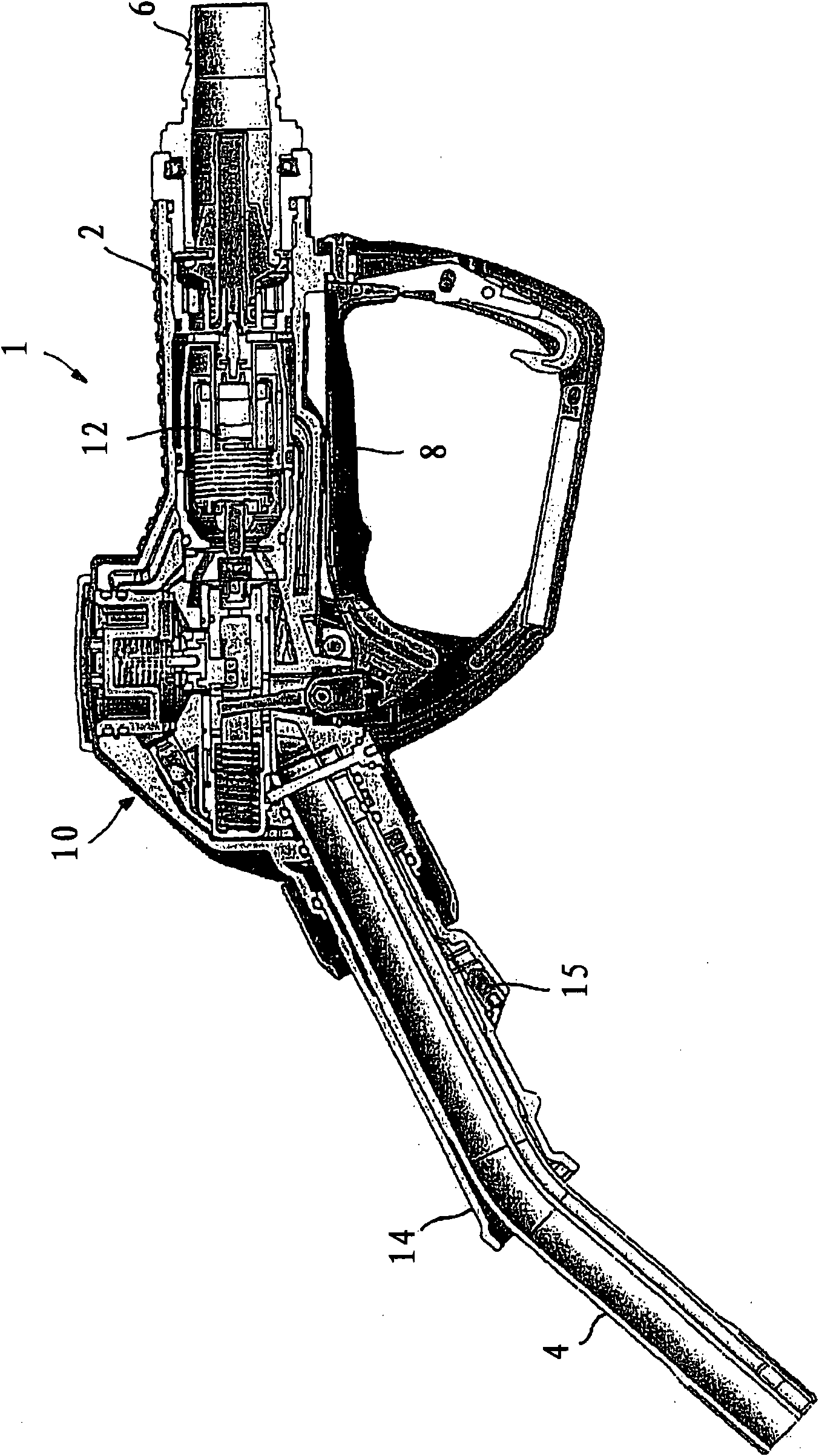
[0025] figure 1 A schematic partial sectional view of a fuel nozzle 1 with a nozzle housing 2 is shown, which has a fuel distribution pipe 4 on the one hand and a pump hose connection 6 on the other. The manual lever 8 shown in the filling position is used to actuate the dispensing valve 10 in a known manner.

[0026] According to the invention, a device 12 for extracting fuel vapors is arranged in the fuel nozzle 1 and during the refueling process the fuel vapors are extracted via a fuel extraction pipe 14 which is arranged coaxially with the fuel distribution pipe 4 And it is connected to the device 12 via a gas flow path not shown in detail.

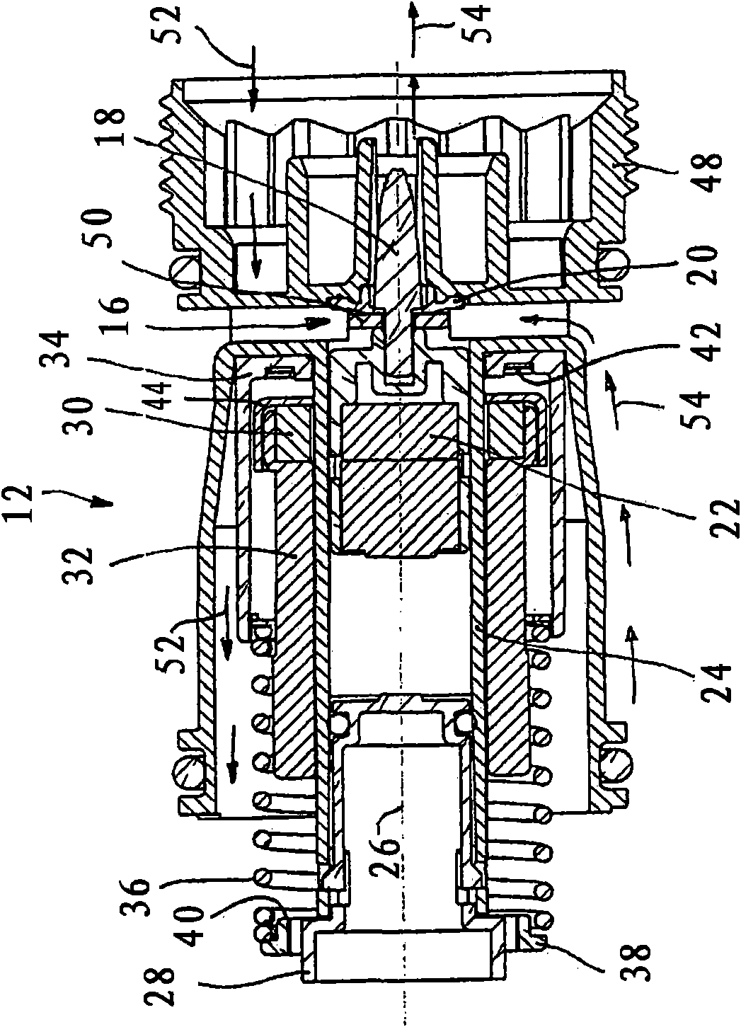
[0027] figure 2 is a longitudinal sectional view illustrating the structure of the device 12 for extracting fuel vapor in the closed position. This device 12 has a gas valve 16, which is connected to a vacuum source via a gas hose (not shown), and which is arranged in the region of the fuel inlet location into the fuel gun housing...


PUM


Abstract

A fuel bowser nozzle includes a nozzle housing, having a fuel dispensing pipe and a pump hose connection, a device for extracting fuel vapours, including a gas valve which can be connected to a vacuum source via a gas hose and which is inserted into the nozzle housing and has fuel flowing round it whenever fuel is flowing. The gas valve has a gas valve body co-operating with a valve seat, the gasvalve body being connected to an operating magnet, which is mounted in a non-ferromagnetic operating magnet housing and is displaceable so as to open and close the gas valve. An actuating magnet which is coupled magnetically to the operating magnet is mounted outside the operating magnet housing and is displaceable between an initial position and a final position defined by a stop. A suspension unit is mounted outside the operating magnet housing, and is displaceable on its mounting so that when fuel flows the unit is subjected to pressure by the fuel and can in this way be moved from an initial position against the action of a restoring spring. The suspension unit is provided with a suspension unit magnet which can be coupled magnetically to the actuating magnet. The operating magnet continuously opens and closes the gas valve depending on its displacement.

Description

technical field [0001] The invention relates to a nozzle with a nozzle housing for refueling with a fuel pump, which nozzle has a fuel distribution pipe on the one hand and a pump hose connection on the other hand, the nozzle has a A device for steam comprising a gas valve capable of being connected via a gas hose to a vacuum source and inserted into the nozzle housing and causing fuel to flow around it whenever the fuel flows, the gas valve having a valve seat cooperating with the an air valve body connected to an operating magnet mounted in a non-ferromagnetic operating magnet housing and movable to open and close the air valve, and wherein the actuating magnet is installed in the operating Outside the magnet housing and movable between an initial position and a final position defined by a stopper, the actuating magnet is magnetically coupled with the operating magnet, such a refueling gun is here regarded as of a known kind. Background technique [0002] Such a fuel nozz...

Claims


Application Information

Patent Timeline
Patent Type & Authority Applications(China)
IPC IPC(8): B67D5/378
CPCB67D2007/545B67D7/54
Inventor U·迈尔J·楚贝
Owner ELAFLEX GUMMI EHLERS
Why Eureka
Try Eureka